6 Hierarchical Modelling
6.1 Introduction
Hierarchical modelling organizes complex objects into a hierarchy of simpler components. This allows for easier manipulation and rendering of complex scenes by breaking them down into manageable parts.
6.1.1 Building Objects
Objects in a hierarchical model are built by combining simpler shapes and components. Each component can be manipulated independently, allowing for flexible and modular design.
Usually, we want an object in its natural coordinates to be centered at the origin, (0,0), or at least to use the origin as a convenient reference point. Then, to place it in the scene, we can use a scaling transform, followed by a rotation, followed by a translation to set its size, orientation, and position in the scene.
saveTransform()
translate(dx,dy) // move object into position
rotate(r)        // set the orientation of the object
scale(sx,sy)     // set the size of the object
     .
     .  // draw the object, using its natural coordinates
     .
restoreTransform()
6.1.2 Stopping Unwanted Interactions
Stopping transforms from interacting with objects, particularly in the context of hierarchical or scene graph transformations, is crucial for maintaining the integrity and accuracy of the graphical representation.
Consider a scenario where you have a robot with a body, arms, and hands. A rotation applied to the arm should not unintentionally rotate the entire robot or other independent objects in the scene.
Alternatively consider the example below of a windmill.
We could hypothetically build this scene using the structure below, where we need build the windmill and the ground. In this case the windmill is made of a base and a top. Lastly to build the top we need to create the blades and the centre.
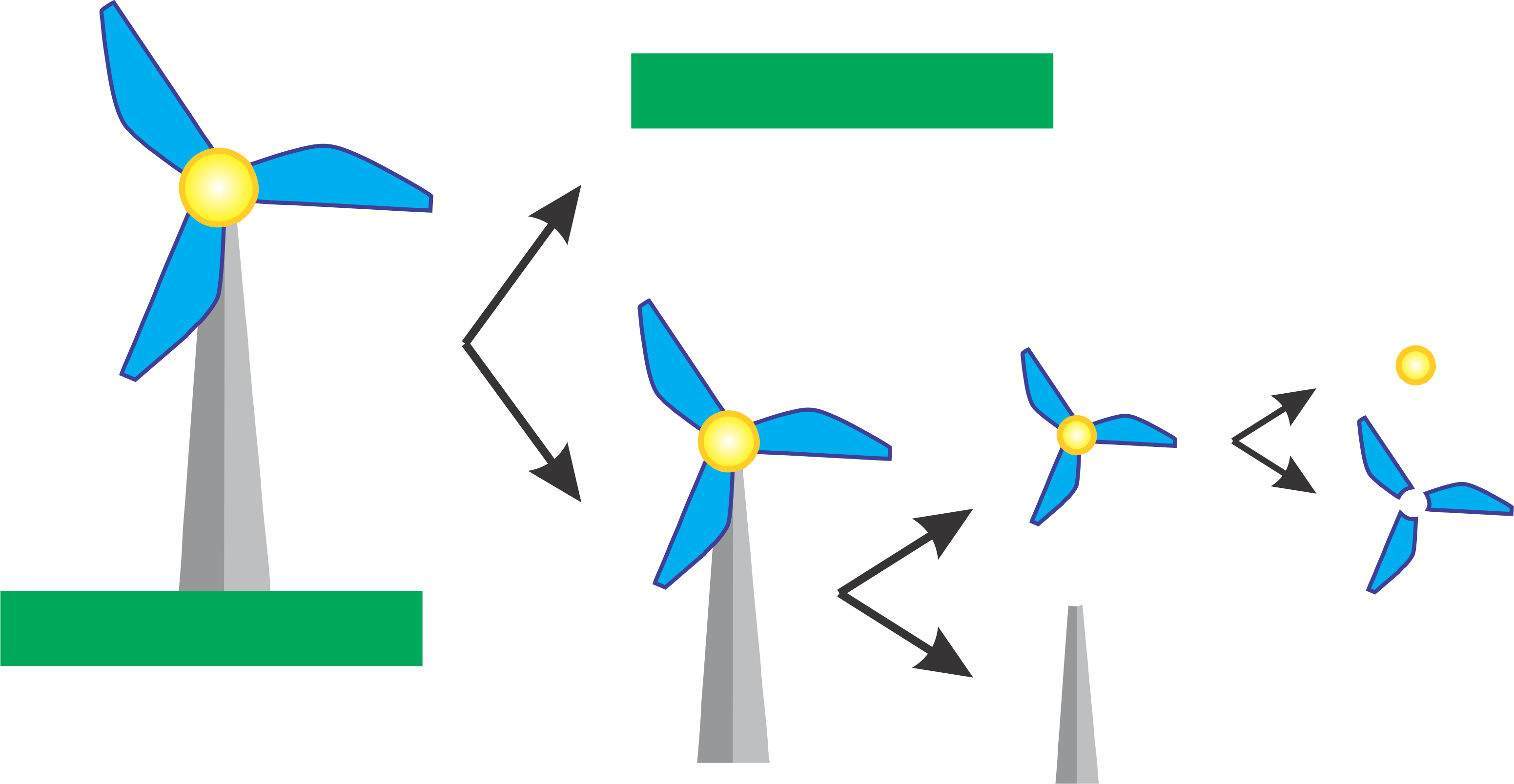
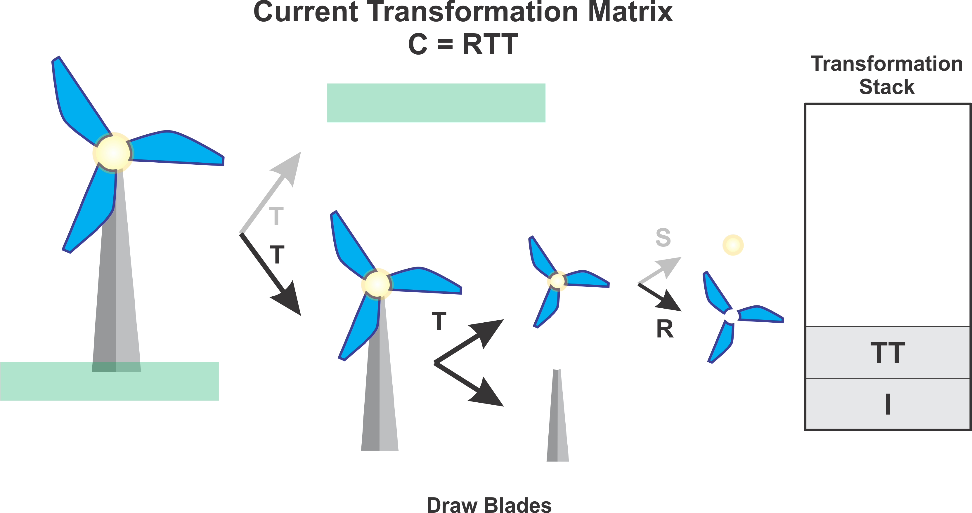
Now if we just consider the blades well wee need to draw each fin. Working backwards we would draw each fin and then rotate by applying a Rotation transformation \(R\). Next we would need to place the windmill relative to the windmill by applying a Translation transformation \(T\). Lastly we would need to place our windmill in the scene by applying another Translation transformation \(T\). Therefore the Transformation matrix that would be applied to the blades would be\(C = RTT\) where \(C\) is the combined Transformation matrix.
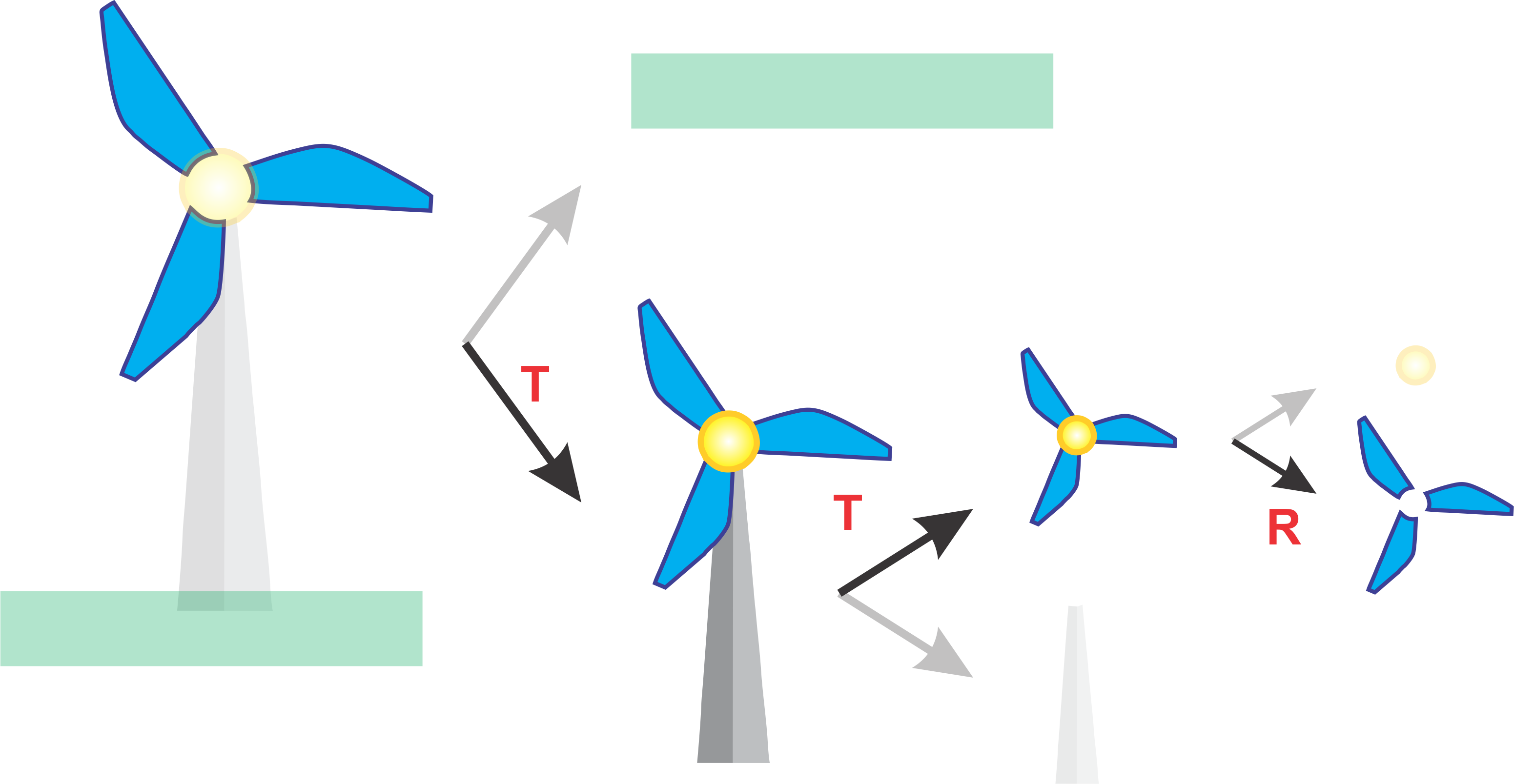
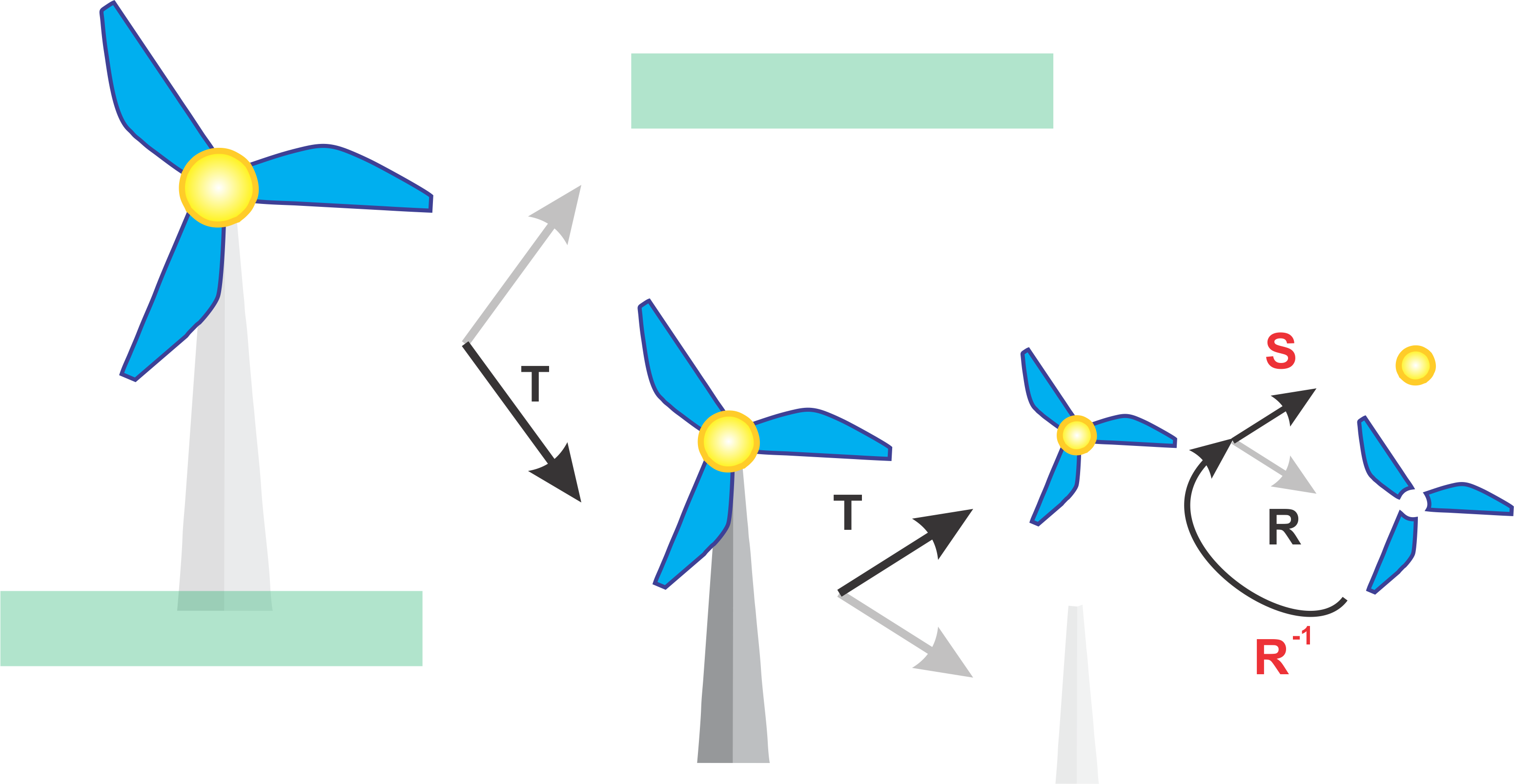
However, what happens now when we want to draw the centre of the windmill (yellow circle). Well we could traverse the graph from the root again, however, this is inefficient an impractical. Ideally we only want to traverse the graph once. To do this we maintain our current transformation and instead backtrack up the graph and then traverse to the next the node. This is similar to the In Order graph traversal you learnt earlier. However when we backtrack we need a way to cancel the previously applied transformations. To do this multiply by the inverse transformation. Therefore the Transformation matrix that would be applied to the blades would be \(C = R^{-1}RTT\) where \(C\) is the combined Transformation matrix to move back up the graph and then finally \(C = SR^{-1}RTT\) to apply the Scaling transformation for the centre.
If we exapand this idea further to drawing the background grass layer, then we need to apply the transformation \(C = T^{-1}T^{-1}S^{-1}SR^{-1}RTT\) where \(C\) is the combined Transformation matrix to traverse all the way back up the graph and then finally \(C = TT^{-1}T^{-1}S^{-1}SR^{-1}RTT\) to apply the final Translation to place the ground in the scene
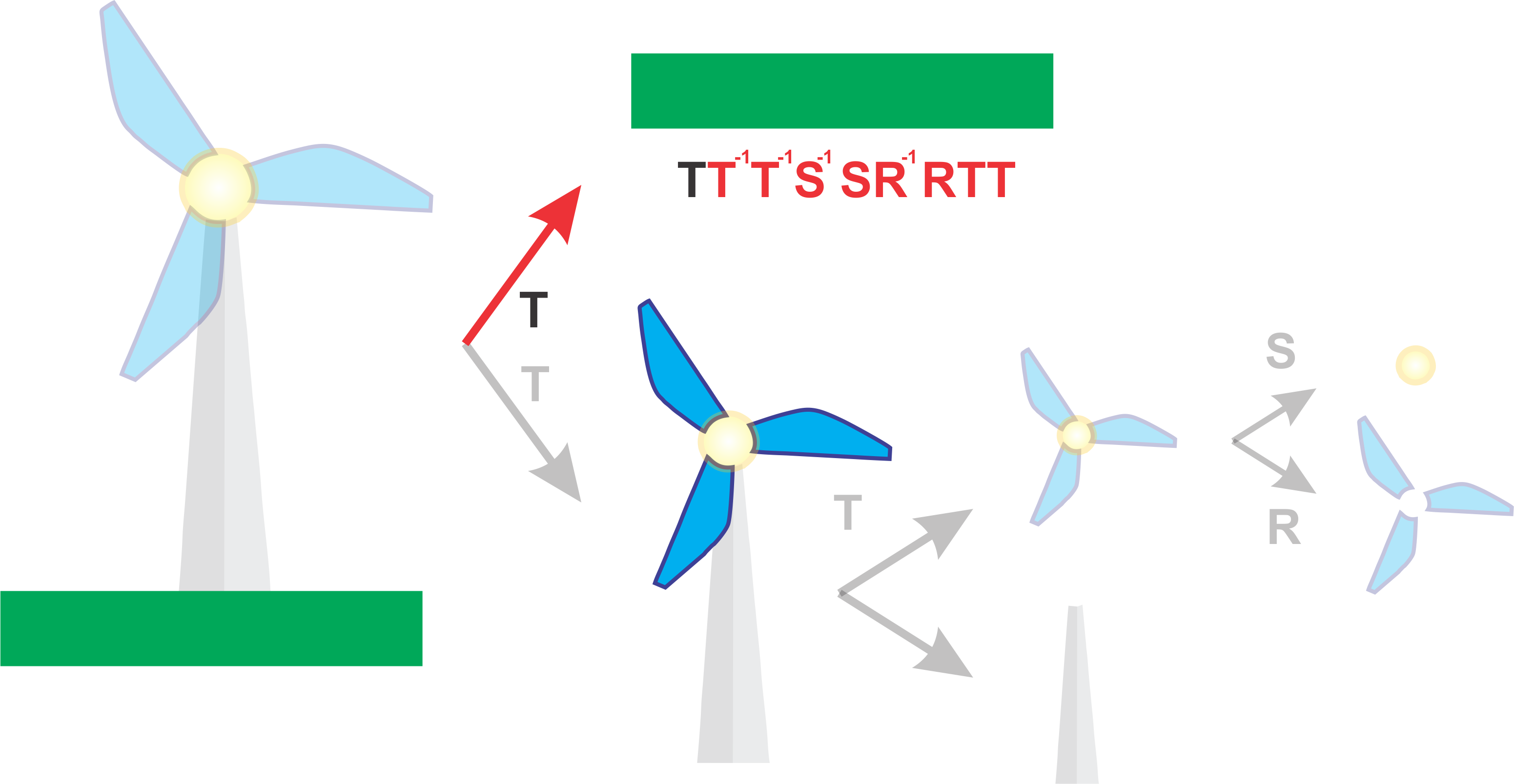
Now if we do not include those inverse transformations then you will get cases where transformations applied to one object such as the rotation of the windmill blades is applied to another object like the background grass. The demo below demonstrates this.
Applying Inverse transformations manually such in the code below can be simple for translation for example
  graphics.translate(0, -2);  // Move the windmill base down
  drawWindmillBase();
  graphics.translate(0, 2);  // Undo Moving the windmill base down
However, this becomes tedious and more difficult for complex transformations such as rotations. Therefore instead we use what is called a Transformation Stack.
6.1.3 Transformation Stack
In computer graphics, the transformation stack is a fundamental concept used to manage and apply transformations such as translation, rotation, and scaling to objects in a hierarchical or scene graph structure. The transformation stack ensures that transformations are applied in the correct order, particularly when dealing with nested objects or scenes where objects are defined relative to each other.
Stack Operations:
Push: When an object’s transformation is about to be applied, the current transformation matrix (which accumulates all previous transformations) is pushed onto the stack. This saves the current state.
Apply Transformation: The new transformation (e.g., translation, rotation) is then applied to the current transformation matrix.
Pop: After the transformations for an object and its children are applied, the transformation stack is popped to restore the previous transformation state before moving on to the next object in the hierarchy.
6.1.3.1 Worked Example
Given our previous example we can achieve the same behaviour using a transformation stack where we push and pop at key moments.
Initially we push the Identity Transformation to the Transformation stack
\[ I = \begin{bmatrix} 1 & 0 & 0 \\ 0 & 1 & 0 \\ 0 & 0 & 1 \end{bmatrix} \]
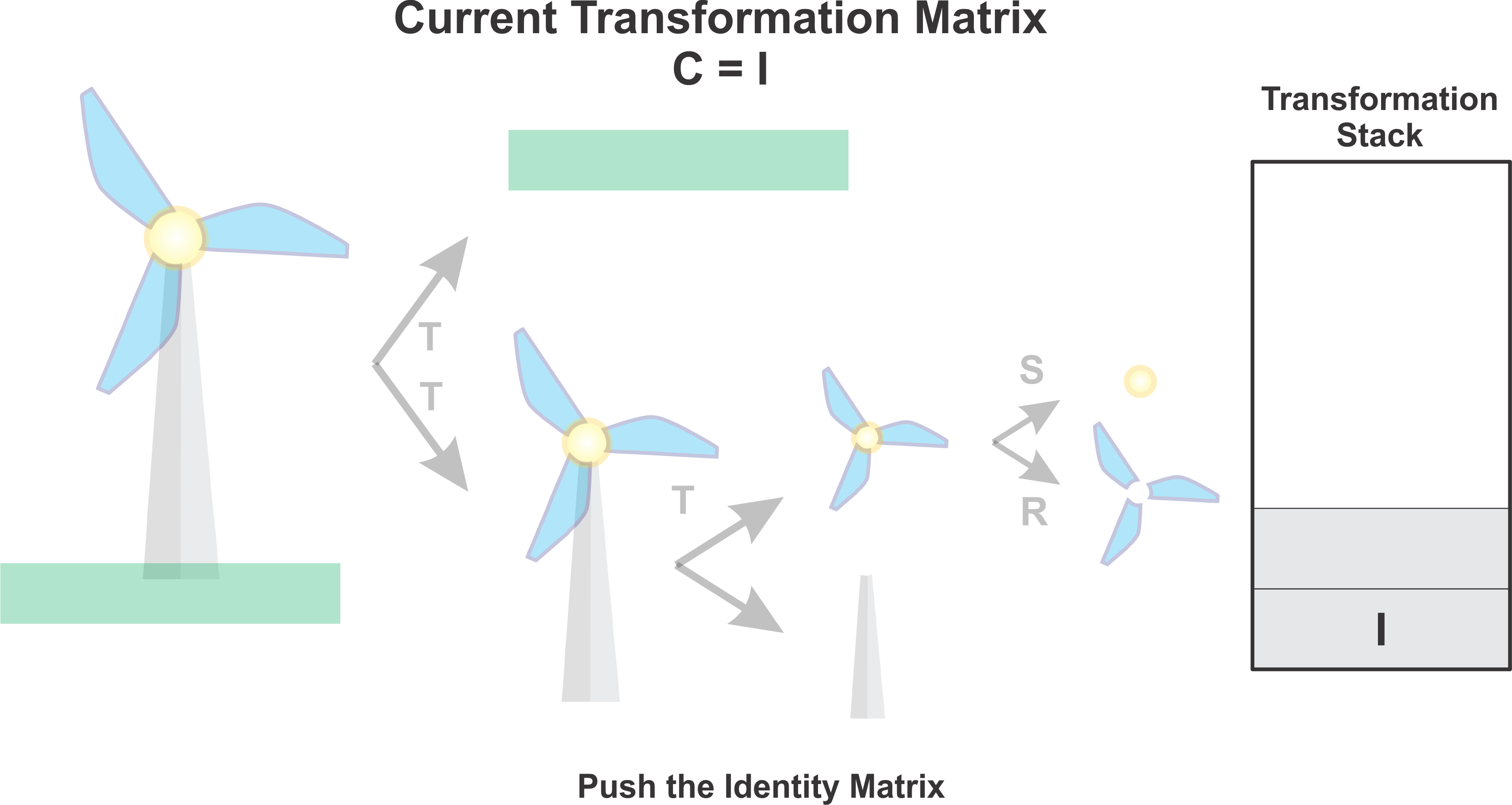
Next we traverse down the hierarchy, drawing any objects along the way. In this case it was the base of the windmill. Afterwards we push the current transfomation matrix \(C = TT\). where \(TT\) represents the two translation transformations we have encountered so far.
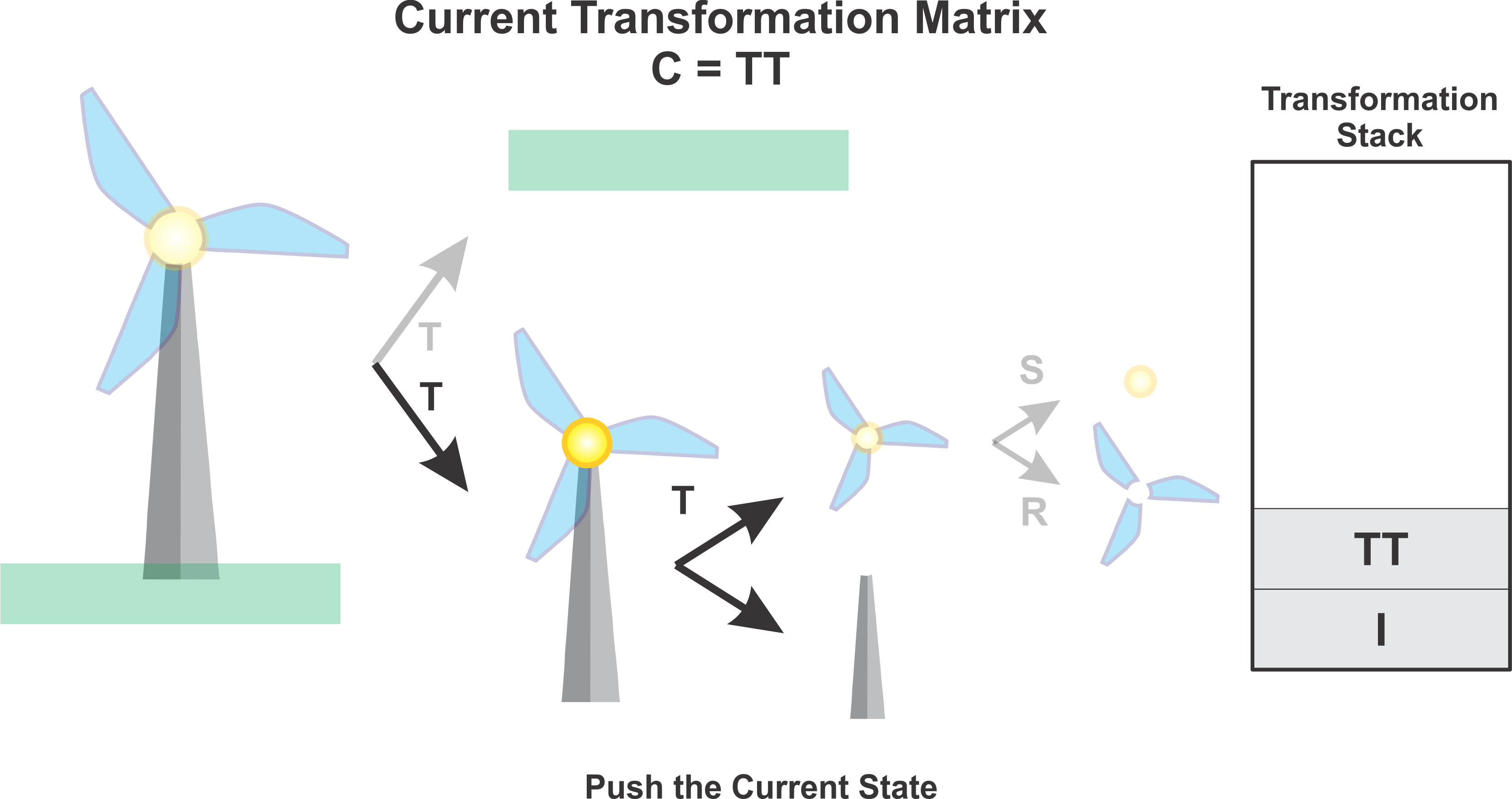
Next we draw the blades after applying a rotation transformation as indicated by \(C = RTT\)
Next we want to draw the centre circle of the windmill. However we do not want to apply the rotation anymore, therefore we pop the transformation stack, updating our current transformation matrix. Hence \(C = TT\).
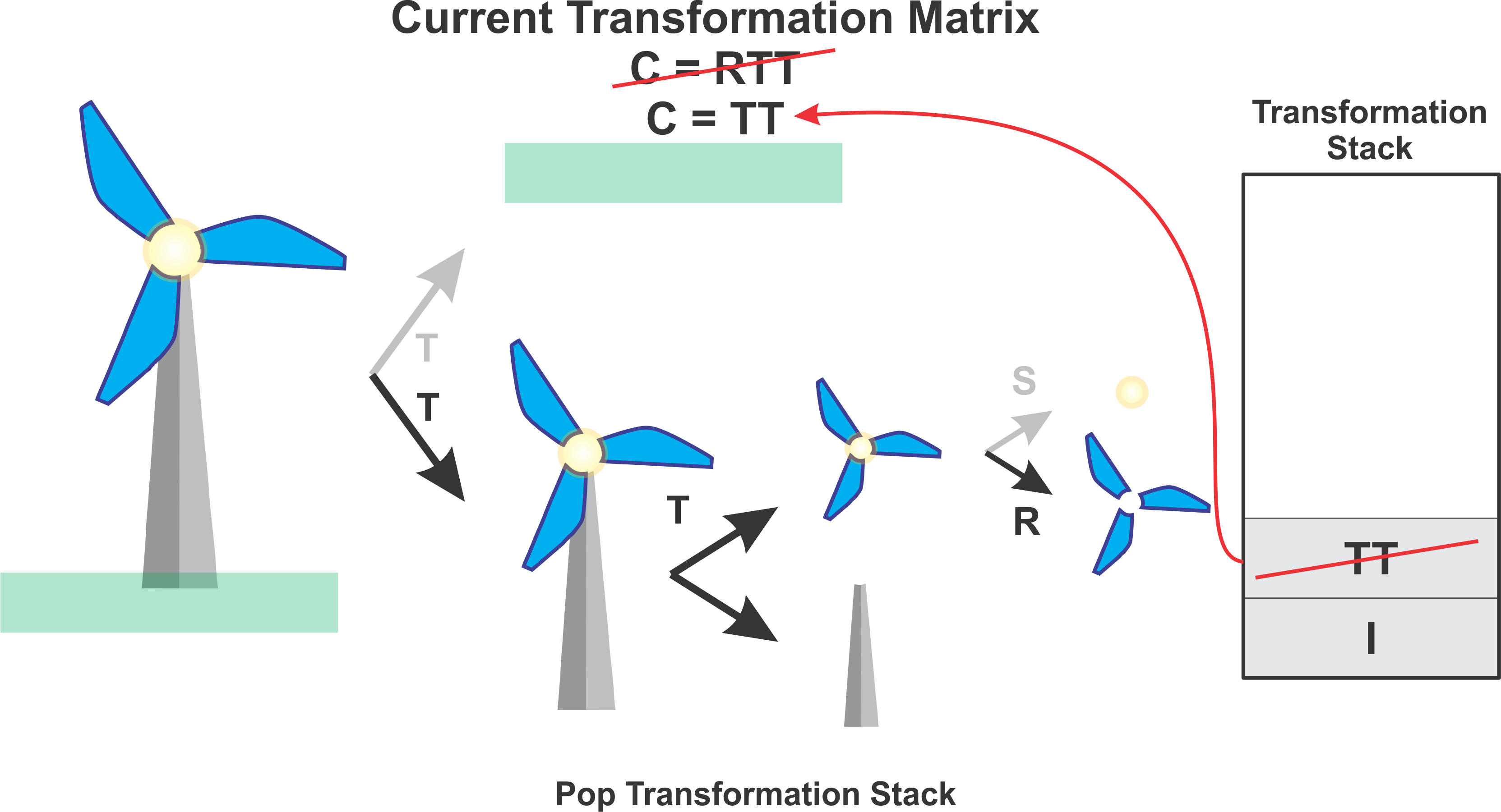
Next we apply the scaling transformation and draw the circle. At this point now \(C = STT\).
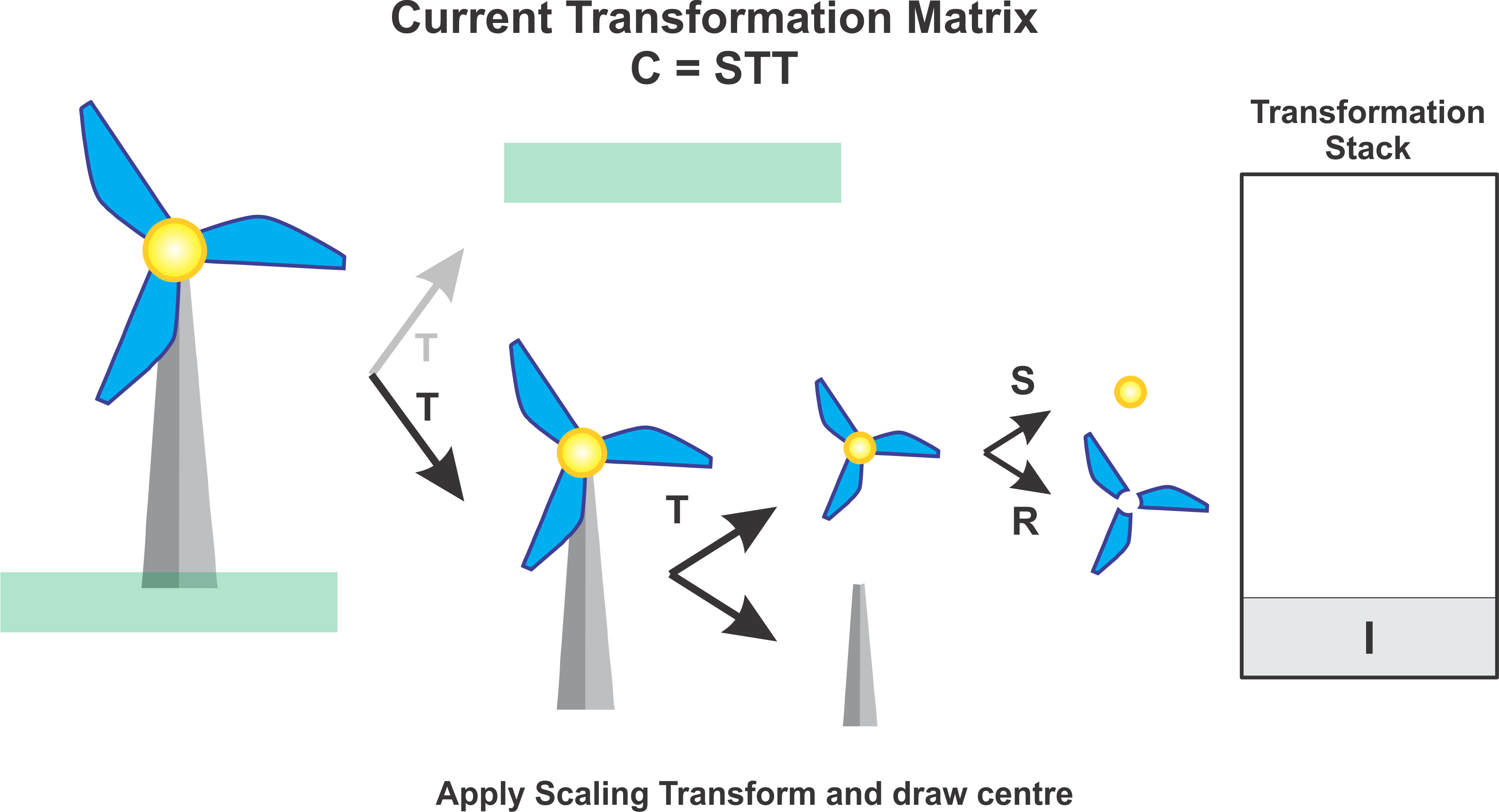
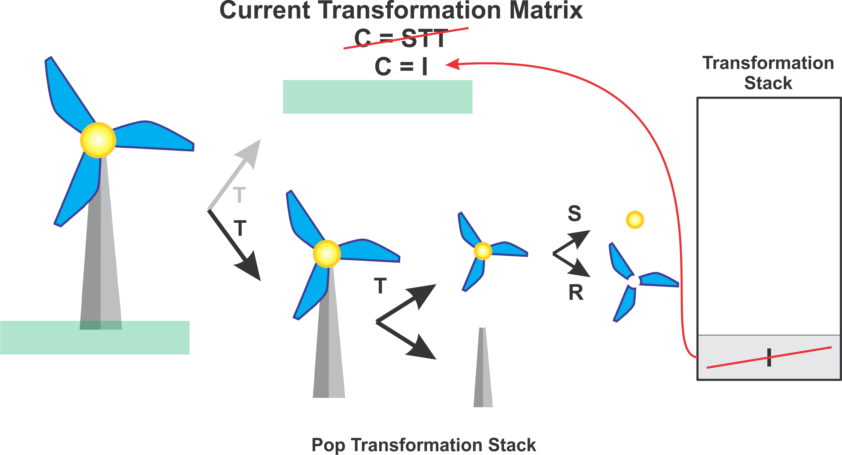
Next we pop the transformation stack again which takes us all the way back to the identity matrix, cancelling both the scaling and translation transformations of the windmill. At this point now \(C = I\).
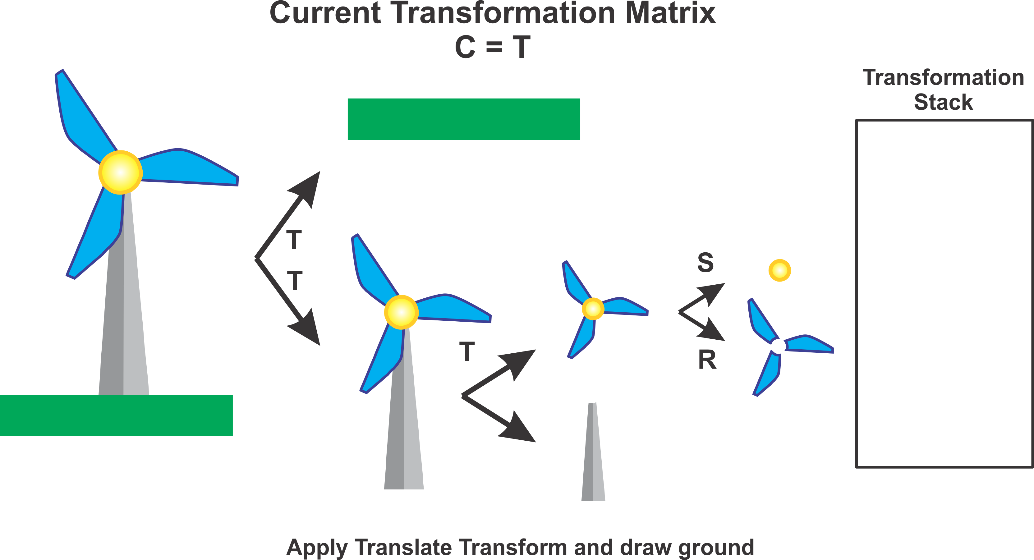
Lastly we apply the translation transformation corresponding to the ground to place that in the scene and finally we draw by applying \(C = T\).
A general practice can be to always push when moving down the hierarchy and to pop when moving up.
6.2 Subroutine
In computer graphics, a subroutine is a reusable block of code that performs a specific task, such as drawing a shape or applying a transformation. Subroutine hierarchies help you break down drawing tasks into smaller, manageable pieces, which can then be composed to create more complex images.
6.2.1 Basic example of a Subroutine
Here’s an example of a simple subroutine to draw a rectangle on an HTML canvas:
function drawRectangle(graphics, x, y, width, height, colour) {
    graphics.fillStyle = colour;
    graphics.fillRect(x, y, width, height);
}
In this function:
-
graphicsis the canvas rendering context. -
xandyare the coordinates of the rectangle’s top-left corner. -
widthandheightare the dimensions of the rectangle. -
colouris the fill color of the rectangle.
6.2.2 Creating Hierachical Structure
To draw more complex scenes, you can create a hierarchy of subroutines. Each subroutine can call other subroutines, building up complexity layer by layer. For example, consider creating a simple drawing of a house.
1. Lowest Level: Basic Shapes
First, define subroutines for basic shapes:
function drawRectangle(graphics, x, y, width, height, color) {
    graphics.fillStyle = color;
    graphics.fillRect(x, y, width, height);
}

function drawTriangle(graphics, x1, y1, x2, y2, x3, y3, color) {
    graphics.fillStyle = color;
    graphics.beginPath();
    graphics.moveTo(x1, y1);
    graphics.lineTo(x2, y2);
    graphics.lineTo(x3, y3);
    graphics.closePath();
    graphics.fill();
}
2. Mid Level: Components of the House
Use these basic shapes to create components of the house:
function drawHouseBase(graphics, x, y, width, height) {
    drawRectangle(graphics, x, y, width, height, 'black'); //base
    drawRectangle(graphics, x, y, width, height, 'brown'); //door
}


function drawRoof(graphics, x, y, width, height) {
    drawTriangle(graphics, x, y, x + width / 2, y - height, x + width, y, 'red');
}
3. Top Level: The Entire House
Finally, create a subroutine to draw the entire house:
    function drawHouse(graphics, x, y, width, height) {
    var baseHeight = height * 0.75;
    var roofHeight = height * 0.25;

    drawHouseBase(graphics, x, y, width, baseHeight);
    drawRoof(graphics, x, y - baseHeight, width, roofHeight);
}
4. Example Usage
To draw a house on the canvas, you can use the drawHouse function:
6.2.3 Applying Transformations
In HTML Canvas, transformations affect the coordinate system used for drawing. The primary transformations are:
- Translate: Moves the coordinate system.
- Rotate: Rotates the coordinate system around the origin.
- Scale: Scales the coordinate system.
- Skew: Skews the coordinate system.
graphics.translate(x, y);
graphics.rotate(angle);
graphics.scale(x, y);
graphics.transform(1, skewY, skewX, 1, 0, 0);
Integrating transformations within subroutines allows you to easily position and manipulate shapes within a hierarchical structure. Here’s an example of how transformations can be used in the hierarchical structure described earlier.
// Get the canvas and its context
var canvas = document.getElementById('myCanvas');
var graphics = canvas.getContext('2d');

// Draw the house at different positions, scales, and rotations
graphics.save();
graphics.translate(50, 150);
graphics.scale(1, 1);
graphics.rotate(0);
drawHouse(graphics, 0, 0, 100, 100);
graphics.restore();

graphics.save();
graphics.translate(200, 150);
graphics.scale(1.5, 1.5);
graphics.rotate(Math.PI / 6);
drawHouse(graphics, 0, 0, 100, 100);
graphics.restore();
6.2.4 Save and Restore
Stopping interactions in hierarchical modelling refers to controlling how interactions (like transformations) affect different levels of the hierarchy. This ensures that changes to parent objects propagate correctly to child objects.
The modeling transformations that are used to place an object in the scene should not affect other objects in the scene. To limit their application to just the one object, we can save the current transformation before starting work on the object and restore it afterwards. How this is done differs from one graphics API to another, but let’s suppose here that there are subroutines saveTransform() and restoreTransform() for performing those tasks. That is, saveTransform will make a copy of the modeling transformation that is currently in effect and store that copy. It does not change the current transformation; it merely saves a copy. Later, when restoreTransform is called, it will retrieve that copy and will replace the current modeling transform with the retrieved transform.
6.2.4.1 The save Function
The save function saves the current state of the canvas context. Each time you call save, the current state is pushed onto a stack.
6.2.4.2 The restore Function
The restore function restores the most recently saved state from the stack. Each time you call restore, the top state is popped from the stack and applied to the canvas context.
6.2.4.3 Example
var canvas = document.getElementById('myCanvas');
var graphics = canvas.getContext('2d');

// Draw a rectangle without any transformations
graphics.fillStyle = 'blue';
graphics.fillRect(10, 10, 100, 50);

// Save the current state
graphics.save();

// Apply transformations and styles
graphics.translate(150, 50);
graphics.rotate(Math.PI / 4);
graphics.fillStyle = 'red';

// Draw a transformed rectangle
graphics.fillRect(0, 0, 100, 50);

// Restore the saved state
graphics.restore();

// Draw another rectangle without transformations
graphics.fillStyle = 'green';
graphics.fillRect(10, 100, 100, 50);-
Initial Drawing State:
- The canvas context is set to draw a blue rectangle at coordinates (10, 10).
-
Saving the State:
- The current state (no transformations, blue fill style) is saved.
-
Applying Transformations:
- The canvas context is translated and rotated, and the fill style is changed to red. These changes will not affect the original state.
-
Drawing with Transformations:
- A red, rotated rectangle is drawn at the new position.
-
Restoring the State:
- The previously saved state (no transformations, blue fill style) is restored. Any changes made after the save call are undone.
-
Drawing After Restore:
- The canvas context is back to its original state, so the next rectangle is drawn without any transformations and with a green fill style.
subroutine drawCart() :
    saveTransform()       // save the current transform
    translate(-1.65,-0.1) // center of first wheel will be at (-1.65,-0.1)
    scale(0.8,0.8)        // scale to reduce radius from 1 to 0.8
    drawWheel()           // draw the first wheel
    restoreTransform()    // restore the saved transform
    saveTransform()       // save it again
    translate(1.5,-0.1)   // center of second wheel will be at (1.5,-0.1)
    scale(0.8,0.8)        // scale to reduce radius from 1 to 0.8
    drawWheel()           // draw the second wheel
    restoreTransform()    // restore the transform
    setDrawingColor(RED)  // use red color to draw the rectangles
    fillRectangle(-3, 0, 6, 2)      // draw the body of the cart
    fillRectangle(-2.3, 1, 2.6, 1)  // draw the top of the cart
6.3 Scene Graphs
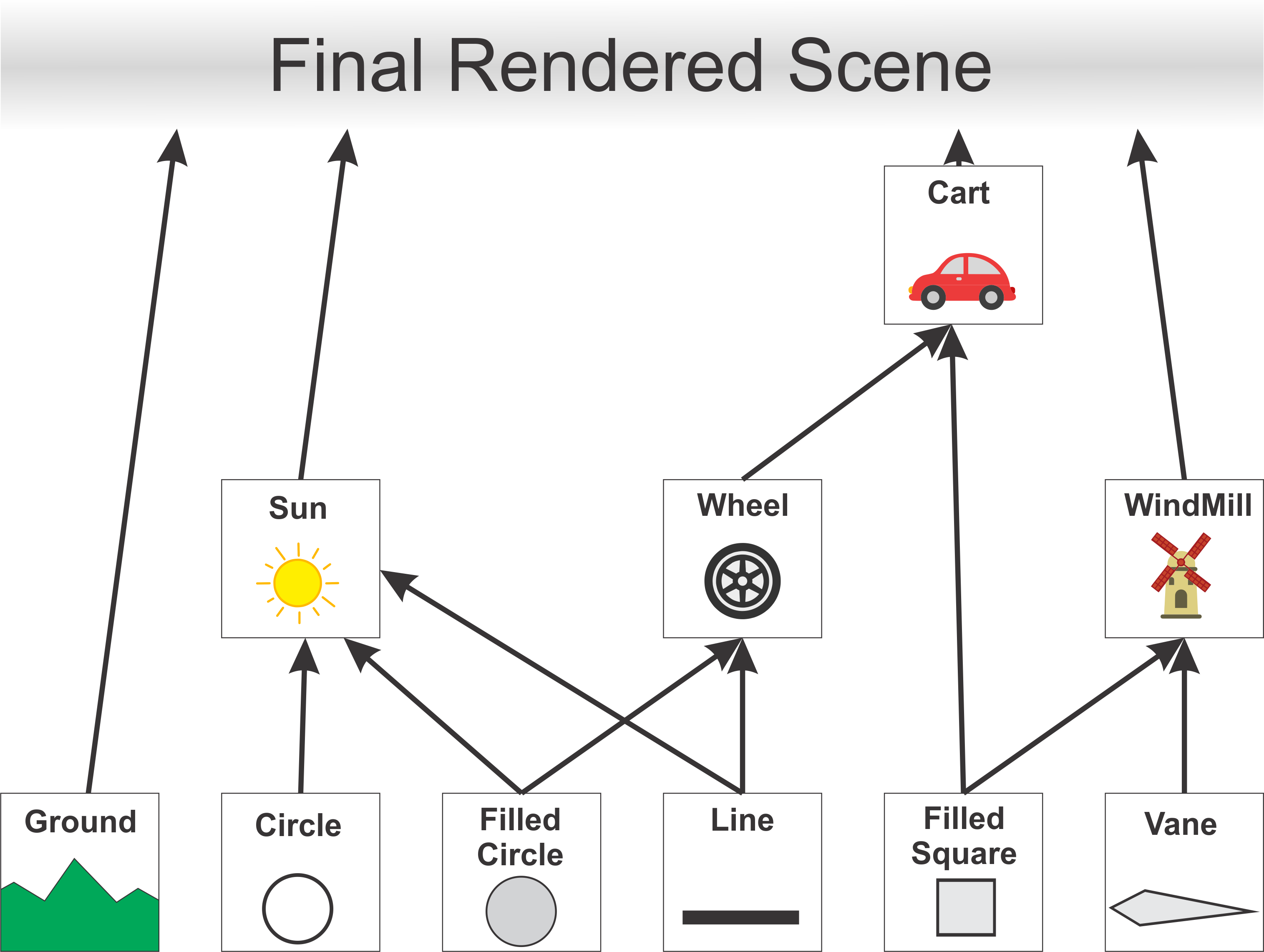
A scene graph is a data structure that represents the objects in a scene, together with attributes of the objects and the modeling transformations that are applied to the objects. An image of the scene is created by traversing the scene graph data structure. A scene graph might exist only conceptually, or it might be an actual data structure in a program. The main purpose for scene graphs is that it allows you to work in an object-orientated framework.
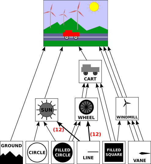
In this drawing, a single object can have several connections to one or more parent objects. Each connection represents one occurrence of the object in its parent object. For example, the “filled square” object occurs as a sub-object in the cart and in the windmill. It is used twice in the cart and once in the windmill. (The cart contains two red rectangles, which are created as squares with a non-uniform scaling; the pole of the windmill is made as a scaled square.) The “filled circle” is used in the sun and is used twice in the wheel. The “line” is used 12 times in the sun and 12 times in the wheel; I’ve drawn one thick arrow, marked with a 12, to represent 12 connections. The wheel, in turn, is used twice in the cart.
In an object-oriented approach, the graphical objects in the scene are represented by program objects. There are many ways to build an object-oriented scene graph API.
In order to create this example using a scene graph we make use of mutliple objects:
-
SceneGraphNode - abstract class which represents a node in a
Scene Graph. -
CompoundObject - subclass of a
SceneGraphNodewhich defines a graphical object. -
TransformedObject - is a
SceneGraphNodethat contains a link to anotherSceneGraphNodeand also contains a modeling transformation that is to be applied to that object.
These objects are useable based upon and html scenegraph API, that I will provide and it is the same one used to make the demos in the labs. It is important to note that this is not the only implementation of Scene Graphs out there.
6.3.1 SceneGraphNode
Below is the base representation of a node in the Scene Graph. You can it is made up of a constructor and a do.draw method.
// The (abstract) base class for all nodes in the scene graph data structure.
function SceneGraphNode() {
    this.fillColor = null;   // If non-null, the default fillStyle for this node.
    this.strokeColor = null; // If non-null, the default strokeStyle for this node.
}
SceneGraphNode.prototype.doDraw = function(g) {
        // This method is meant to be abstract and must be OVERRIDDEN in an actual
        // object. It is not meant to be called; it is called by draw().
    throw "doDraw not implemented in SceneGraphNode"
}
Anything you wish to render needs to be represented by a Scene Graph node and hence you have Scene Grap Node representations for all the basic primitives. For example for a line below:
6.3.2 CompoundObject
Defines a subclass, CompoundObject, of SceneGraphNode to represent an object that is made up of sub-objects. Initially, there are no sub-objects. Objects are added with the add() method.
function CompoundObject() {
    SceneGraphNode.call(this);  // do superclass initialization
    this.subobjects = [];  // the list of sub-objects of this object
}
CompoundObject.prototype = new SceneGraphNode(); // (makes it a subclass!)
CompoundObject.prototype.add = function(node) {
        // Add node a subobject of this object.  Note that the
        // return value is a reference to this node, to allow chaining
        // of method calls.
    this.subobjects.push(node);
    return this;
}
CompoundObject.prototype.doDraw = function(g) {
        // Just call the sub-objects' draw() methods.
    for (var i = 0; i < this.subobjects.length; i++)
        this.subobjects[i].draw(g);
}
We can added renderable objects to a CompoundObject, meaning anything which extends the SceneGraphNode class. For example:
var sunTemp = new CompoundObject();
sunTemp.add( filledCircle );  // the face of the sun
sunTemp.add( new TransformedObject(circle).setColor("#DD8800") ); // outlines the face
You can even add other CompoundObjects to a CompoundObject.
6.3.3 TransformedObject
Define a subclass, TransformedObject, of SceneGraphNode that represents an object along with a modeling transformation to be applied to that object. The object must be specified in the constructor. The transformation is specified by calling the setScale(), setRotate() and setTranslate() methods. Note that each of these methods returns a reference to the TransformedObject as its return value, to allow for chaining of method calls. ** NB - The modeling transformations are always applied to the object in the order scale, then rotate, then translate.**
function TransformedObject(object) {
        SceneGraphNode.call(this);  // do superclass initialization
        this.object = object;
        this.rotationInDegrees = 0;
        this.scaleX = 1;
        this.scaleY = 1;
        this.translateX = 0;
        this.translateY = 0;
    }
    TransformedObject.prototype = new SceneGraphNode();  // (makes it a subclass!)
    TransformedObject.prototype.setRotation = function(angle) {
           // Set the angle of rotation, measured in DEGREES.  The rotation
           // is always about the origin.
        this.rotationInDegrees = angle;
        return this;
    }
    TransformedObject.prototype.setScale = function(sx, sy) {
           // Sets scaling factors.
        this.scaleX = sx;
        this.scaleY = sy;
        return this;
    }
    TransformedObject.prototype.setTranslation = function(dx,dy) {
           // Set translation mounts.
        this.translateX = dx;
        this.translateY = dy;
        return this;
    }
    TransformedObject.prototype.doDraw = function(g) {
            // Draws the object, with its modeling transformation.
        g.save();
        if (this.translateX != 0 || this.translateY != 0) {
            g.translate(this.translateX, this.translateY);
        }
        if (this.rotationInDegrees != 0) {
            g.rotate(this.rotationInDegrees/180*Math.PI);
        }
        if (this.scaleX != 1 || this.scaleY != 1) {
            g.scale(this.scaleX, this.scaleY);
        }
        this.object.draw(g);
        g.restore();
    }
6.3.4 How to make a car
Step 1: Define the root of the Scene Graph
var world;  // A SceneGraphNode representing the entire scene defined globally.

function createWorld() {
    world = new CompoundObject();  // Root node for the scene graph.
}
Step 2: Start building the hierarchy from the bottom up (Wheel)
- Define a CompoundObject for a wheel
- Set the colour of the wheel
- Add circles to represent the tyre
wheelTemp.add( new TransformedObject(filledCircle).setScale(2,2) );
wheelTemp.add( new TransformedObject(filledCircle).setScale(1.6,1.6).setColor("#CCCCCC") );
wheelTemp.add( new TransformedObject(filledCircle).setScale(0.4,0.4) );- Add spokes to represent the rims
for (let i = 0; i < 12; i++) {  // add the 12 spokes
    wheelTemp.add( new TransformedObject(line).setRotation(i*30) );
}- Define a global object to represent the wheel object
Step 3: Build the chassis
let cart;

function createWorld() {
  let cartTemp = new CompoundObject();
  cartTemp.setColor("red"); // color for the rectangular body of the cart
  cartTemp.add( new TransformedObject(wheel).setScale(0.8,0.8).setTranslation(1.65,-0.1) );
  cartTemp.add( new TransformedObject(wheel).setScale(0.8,0.8).setTranslation(-1.65,-0.1) );
  cartTemp.add( new TransformedObject(filledRect).setScale(6,1.5).setTranslation(0,1) ); // the body of the cart
  cartTemp.add( new TransformedObject(filledRect).setScale(2.6,1).setTranslation(-1,2) ); // the top of the cart
  cart = new TransformedObject(cartTemp).setScale(0.3,0.3);
Step 4: Add the cart to the world
The final function should look something like this
var world;  // A SceneGraphNode representing the entire picture.  This should
                // be created in the createWorld() method.


let cart;   // TransformedObjects that are animated.
let wheel;

function createWorld() {

        world = new CompoundObject();


        let wheelTemp = new CompoundObject();
        wheelTemp.setColor("black"); // color for all but one of the subobjects
        wheelTemp.add( new TransformedObject(filledCircle).setScale(2,2) );
        wheelTemp.add( new TransformedObject(filledCircle).setScale(1.6,1.6).setColor("#CCCCCC") );
        wheelTemp.add( new TransformedObject(filledCircle).setScale(0.4,0.4) );
        for (let i = 0; i < 12; i++) {  // add the 12 spokes
           wheelTemp.add( new TransformedObject(line).setRotation(i*30) );
        }
        wheel = new TransformedObject(wheelTemp);

        let cartTemp = new CompoundObject();
        cartTemp.setColor("red"); // color for the rectangular body of the cart
        cartTemp.add( new TransformedObject(wheel).setScale(0.8,0.8).setTranslation(1.65,-0.1) );
        cartTemp.add( new TransformedObject(wheel).setScale(0.8,0.8).setTranslation(-1.65,-0.1) );
        cartTemp.add( new TransformedObject(filledRect).setScale(6,1.5).setTranslation(0,1) ); // the body of the cart
        cartTemp.add( new TransformedObject(filledRect).setScale(2.6,1).setTranslation(-1,2) ); // the top of the cart
        cart = new TransformedObject(cartTemp).setScale(0.3,0.3);

        world.add( cart );
    }
6.3.5 Save / Restore
How does the interrupt stack work in conjuction with a Scene Graph Hierarchy. Consider the following hierarchy
Here’s how it works in the context of a scene graph node hierarchy:
- Start at the Root Node:
The traversal begins at the root node of the scene graph, which might represent the entire scene or a major object within it. The root node’s transformation is applied first. This might involve moving the entire scene or object to a particular location in the world.
- Push Transformation onto the Stack:
When you move down to a child node, you push the current transformation onto the stack. This operation effectively “saves” the current transformation state before applying additional transformations specific to the child node.
- Apply Child Node Transformation:
The child node’s transformation is applied on top of the transformation stack. This is a combined transformation that takes into account the parent’s transformations. This ensures that the child node’s transformations are relative to its parent’s coordinate system, not the global coordinate system.
- Recursively Traverse the Hierarchy:
This process continues as you move down the hierarchy, with each node’s transformation being applied relative to its parent. Each time you move to a new node, you push the current transformation stack, apply the node’s transformation, and continue the traversal.
- Pop Transformation from the Stack:
Once you finish processing a node and its children, you pop the transformation from the stack. This operation restores the previous transformation state, which is necessary for correctly transforming sibling nodes.
- Rendering:
When you reach a leaf node (a node with no children), the combined transformation from the root down to this node is applied, and the object represented by this node is rendered in the correct position, orientation, and scale in the world.
6.3.5.1 Example
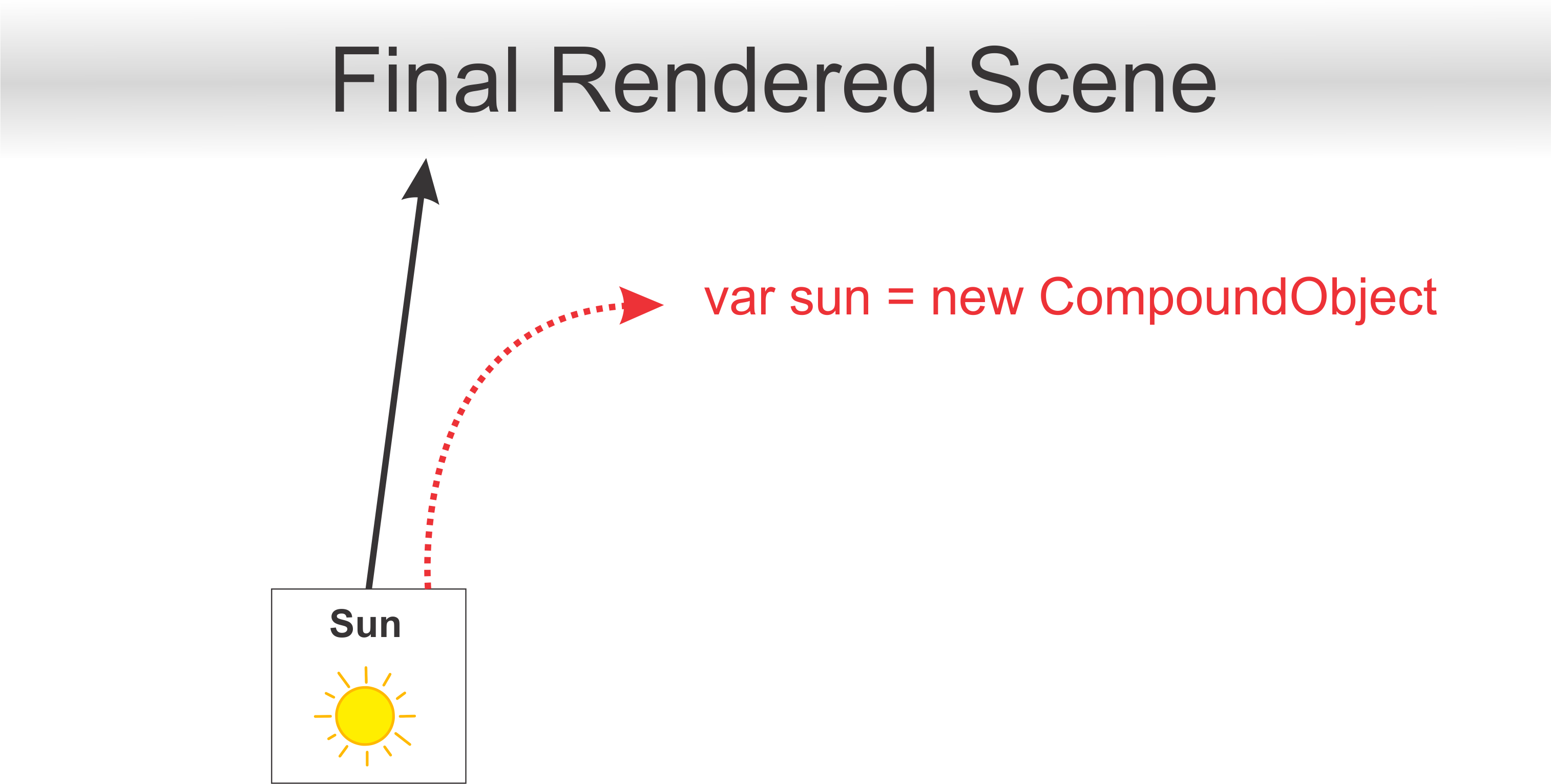
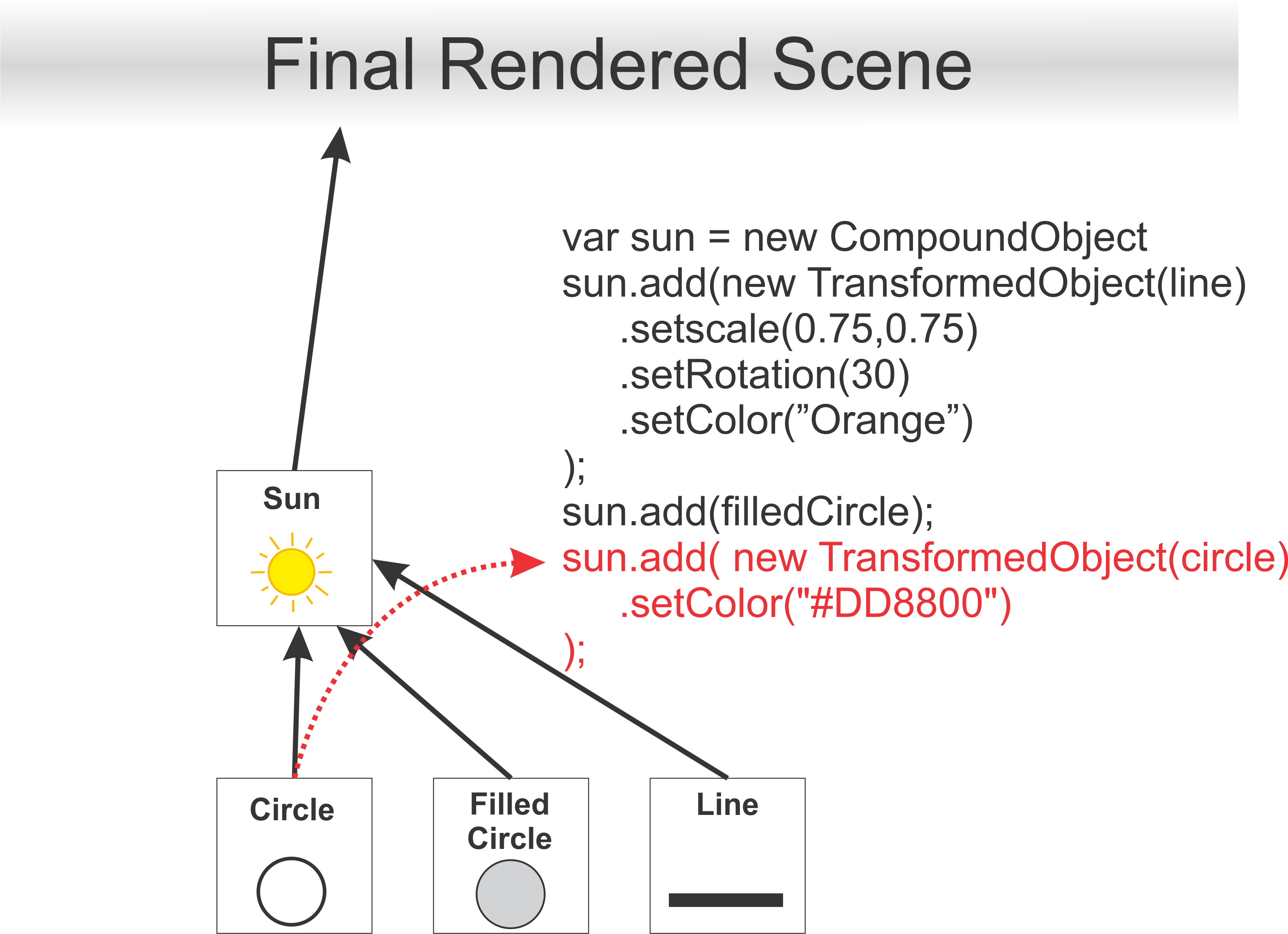
In particular how we would draw the sun.
Firstly we need to define a compoundObject
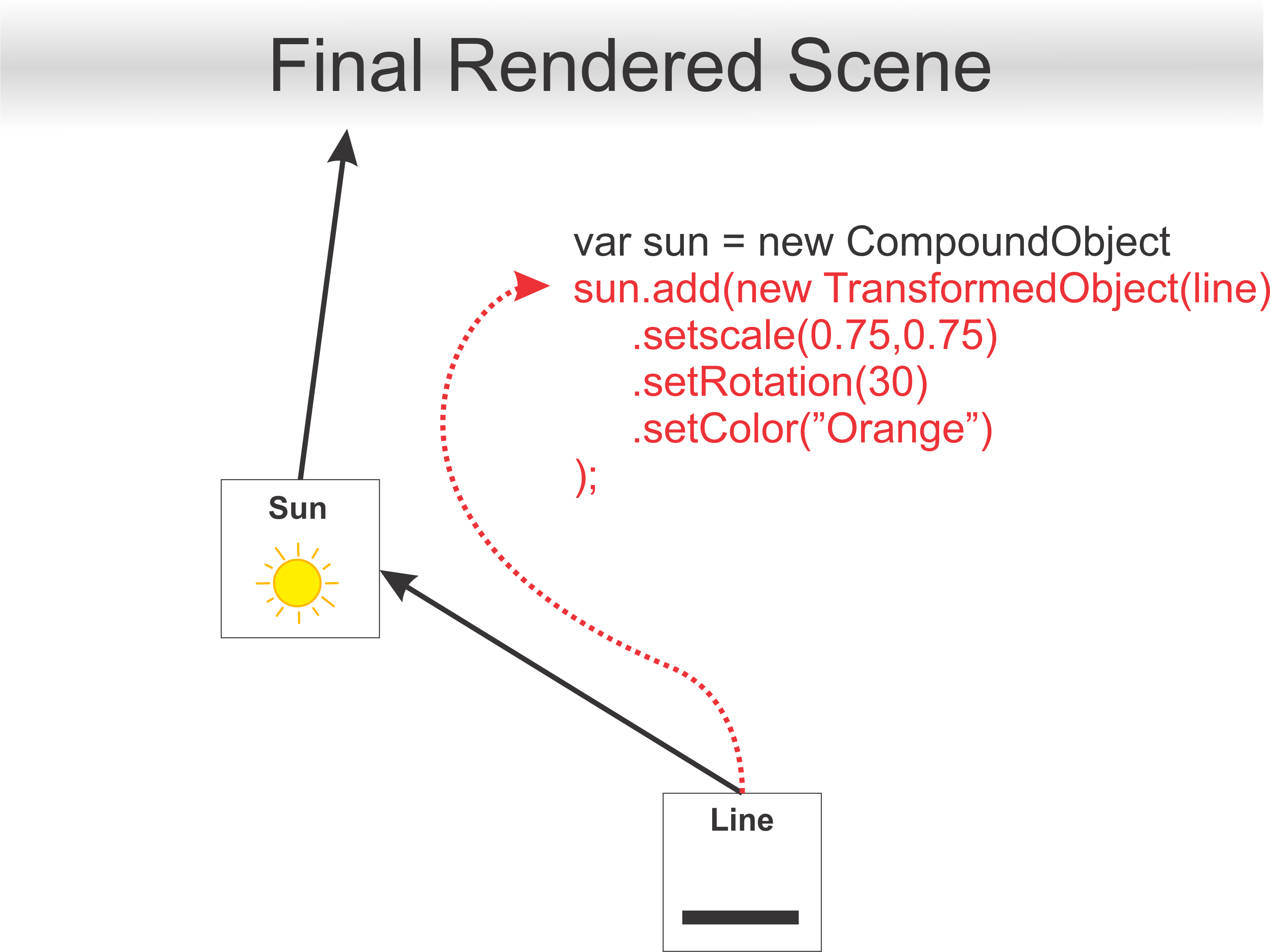
Next, we add a Transformed Object for each of the suns rays
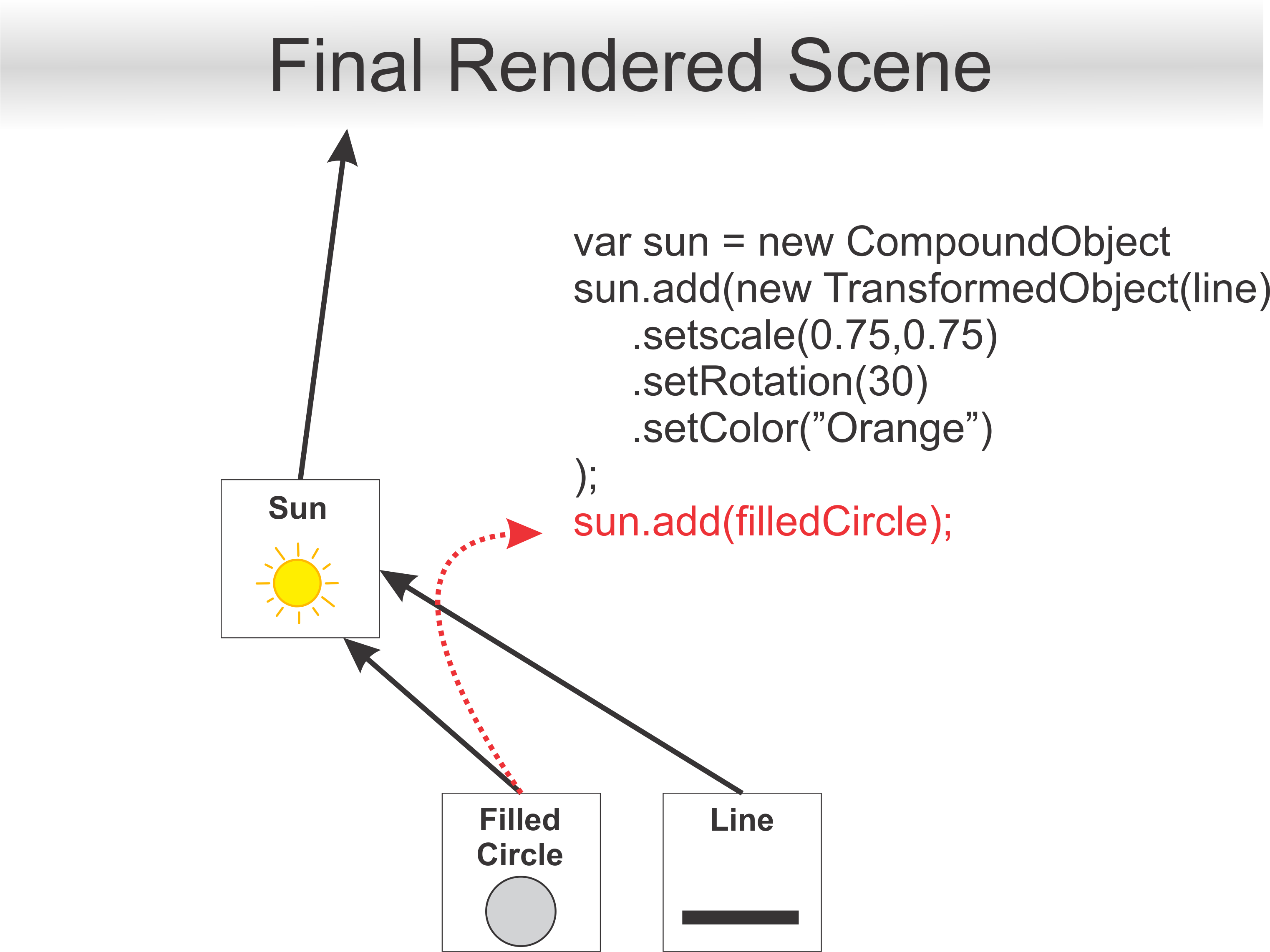
Next, we can simply add a scenegraph node such a filled circle as we do not intend to apply any transformations directly to it. Additionally, this node does not have sub-components, therefore it is not a CompoundObject.
Lastly, we add a transformed object for the circle which defines the outline of the sun.
The key idea to understand is that all of those transforms that we applied to that branch would affect connected members lower down. However, none of those transformations would affect the Cart, Ground or Windmill Branches of the Tree.
6.4 Animation
Animation in computer graphics is the process of creating motion by displaying a sequence of images or frames. Techniques like keyframing, interpolation, and motion capture are used to create realistic animations. Transformations play a crucial role in moving and deforming objects over time to achieve the desired effects.
 /**
     * This will be called before each frame is drawn.
     */
    function updateFrame() {
        frameNumber++;
        cart.setTranslation(-3 + 13*(frameNumber % 300) / 300.0, 0);
        wheel.setRotation(-frameNumber*3.1);
    }
Here we use a framenumber to manipulate how we draw our objects by influencing the transforms. Therefore based on the framenumber we will get a different position for cart.setTranslation as well as a different rotation for wheel.setRotation.
6.4.1 Evolution of Animation in Games
6.4.1.1 Sprite Animations
Sprites were used extensively in arcade and console games like “Super Mario Bros.” (1985). These were 2D images or frames that were animated by changing the sprite displayed on the screen at each step in the animation.
![]()
![]()
![]()
6.4.1.2 Stop Motion
Stop motion is an animation technique that involves capturing individual frames of physical objects in various positions and then playing these frames in sequence to create the illusion of movement. It is a meticulous and labour-intensive process, where animators carefully manipulate objects or figures, often made of clay, puppets, or other materials, to create each frame.
Examples
- Caroline (2009)
- Fantastic Mr. Fox (2009)
- Neverhood (1996)

6.4.1.3 Parallax Scrolling
This technique created an illusion of depth by having background layers move at different speeds, enhancing 2D animation in games like “Sonic the Hedgehog” (1991).


6.4.1.4 Keyframe Interpolation
In games like “Tomb Raider” (1996), keyframes were used to animate 3D models by setting key poses for various actions such as walking, running, and jumping. Game engines interpolate between keyframes to create smooth transitions, allowing for more realistic and continuous animations.
Different interpolation techniques allow animators to control the timing and spacing of animations, making transitions more natural and aesthetically pleasing. Each type of interpolation offers different levels of control and smoothness, enabling a wide range of effects and styles in animated content.
6.4.1.5 Motion Tracking
Motion capture (often abbreviated as mocap) is a technique used to record and translate the movement of real-life actors into digital models. The process begins with actors or performers wearing specialized suits equipped with markers or sensors. These markers track the movements of the performer’s body, and sometimes their facial expressions, if facial capture is involved.
Small reflective or LED markers are attached to the suit. These markers are tracked by multiple cameras set up around the motion capture space. The cameras capture the movement of the markers in three-dimensional space. The data from the cameras or sensors is processed by software that translates the movement into digital animation data. This data can then be applied to 3D models, making them move in the same way as the performer.
First used in “Tekken 3” (1997), motion capture involved recording real actors’ movements to create lifelike animations for characters. Widely used in modern games and movies for cutscenes and character motion such Uncharted 4.
6.4.1.6 Inverse Kinematics
Inverse Kinematics (IK) is a technique used in computer graphics and animation, including video games, to calculate the joint configurations needed for a character’s limb to reach a target position. This is particularly useful for animating articulated figures, such as humanoid characters, where you need to determine the positions of various joints (e.g., elbows, knees) to achieve a desired end effector position (e.g., a hand or foot reaching a specific point).
6.4.1.6.1 Key Concepts of Inverse Kinematics
-
Forward Kinematics (FK) vs. Inverse Kinematics (IK):
-
Forward Kinematics: Involves moving each joint individually from the base to the tip of a chain (e.g., shoulder to hand), which can be tedious and difficult to control precisely. In the following picture movement with arms set to IK but leg to FK.
-
Inverse Kinematics: Starts with the end effector (e.g., hand or foot) and calculates the joint angles needed to achieve the desired position, simplifying the animation process and creating more natural movement. In the following picture movement with arms and legs set to IK.
-
Forward Kinematics: Involves moving each joint individually from the base to the tip of a chain (e.g., shoulder to hand), which can be tedious and difficult to control precisely. In the following picture movement with arms set to IK but leg to FK.
-
End Effector:
- The part of the limb or chain that interacts with the environment or reaches for a target. For a humanoid character, this might be a hand or foot.
-
IK Chain:
- A sequence of joints and bones (e.g., arm or leg) that the IK algorithm controls to reach the target position with the end effector.
6.4.1.6.2 How Inverse Kinematics Works
-
Target Position:
- The animator sets a target position for the end effector, such as a hand reaching for a door handle or a foot touching the ground.
-
IK Solver:
- An algorithm calculates the angles and rotations for each joint in the IK chain to reach the target position. Common IK solvers include the Jacobian-based methods, CCD (Cyclic Coordinate Descent), and FABRIK (Forward and Backward Reaching Inverse Kinematics).
-
Constraints:
- IK systems often include constraints to ensure realistic motion, such as limits on joint angles, to prevent unnatural bending or twisting.
This technique, was used in games like “Shadow of the Colossus” (2005), allowed characters to interact with their environments more realistically by adjusting limb positions dynamically.
6.4.1.7 Procedural Animation
Procedural animation is a technique in computer graphics and animation where movements are generated algorithmically in real-time rather than being pre-animated by an artist.
6.4.1.7.1 Techniques in Procedural Animation
-
Physics-Based Animation:
- Ragdoll Physics: Uses physics engines to simulate realistic body movements and reactions upon impacts or falls.
-
Simulations: Real-time simulations of physical phenomena, such as fluid dynamics or cloth movement, enhance realism.
-
Behavioral Animation:
- AI-Driven Movements: Characters’ actions are determined by artificial intelligence algorithms, allowing them to react dynamically to the game world and player actions.
-
Algorithmic Animation:
- Noise Functions: Used to create natural, organic movements, such as the swaying of trees or undulating water surfaces.
-
Procedural Walk Cycles: Algorithms generate walk cycles based on character speed, direction, and terrain, allowing for seamless transitions between different movements.
6.4.1.7.2 Applications in Video Games
-
Character Animation:
- Locomotion Systems: Characters adapt their walking, running, or jumping animations based on terrain type or slope, as seen in games like “The Elder Scrolls V: Skyrim” and “The Witcher 3: Wild Hunt.”
-
Physics-Based Movement: Characters can react naturally to forces, such as gravity or collisions, using physics-based procedural animation.
-
Environmental Interaction:
- Dynamic Environments: Objects like trees, water, or grass can be animated procedurally to respond to environmental factors such as wind or player interactions.
-
Crowd Simulation:
-
Complex Systems: Procedural animation is used to animate large groups of characters or entities, ensuring realistic crowd behaviours without manually animating each individual.
-
Complex Systems: Procedural animation is used to animate large groups of characters or entities, ensuring realistic crowd behaviours without manually animating each individual.
-
Combat and Creature Behaviour:
- Adaptive Combat: Characters and creatures can adapt their combat animations to different opponents and environments, creating more engaging and varied encounters.
-
Procedural Creatures: Games like “Spore” use procedural animation to allow creatures to move and interact in ways consistent with their generated anatomy.
Games like “Rain World” used procedural generation to create varied and dynamic animations without needing hand-crafted content for each scenario.