11 Textures
11.1 Introduction
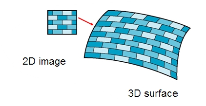
Texture is the visual or tactile surface characteristics and appearance of something. The most common type is image texture. When an image texture is applied to a surface, the surface color varies from point to point.

Here is a nice additional resource
https://jcsites.juniata.edu/faculty/rhodes/graphics/texturemap.htm
11.2 Process
Using image textures in computer graphics is a key process that enhances the visual quality of 3D models and environments by adding detail, realism, and surface complexity without the need for more geometry. Here’s how the process generally works:
-
Texture Creation: Textures can be created in various ways, including photographing real-world objects, painting textures in a digital art program, or generating them procedurally within graphics software. Textures can represent not just color, but also details like bumps, reflectivity, and transparency.
- HDRi (High Dynamic Range Imaging)
- Algorithmically Generated Textures
- HDRi (High Dynamic Range Imaging)
-
Texture Mapping: This step involves mapping the 2D texture images onto the surface of a 3D model. The main techniques for texture mapping include:
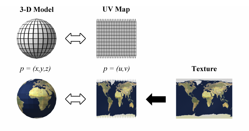
- UV Mapping: This involves unwrapping the 3D model into a 2D space and defining how each vertex of the model corresponds to a point on the 2D texture image. UV maps are akin to the pattern pieces in sewing.
- Projection Mapping: Here, the texture is projected onto the object using a specific method such as planar, cylindrical, or spherical mapping. This can be useful for simple shapes or when UV mapping would be too complex.
Texture Editing and Adjustment: Once the texture is mapped, it may need adjustments to align correctly on the model or to repeat seamlessly. Tools within 3D software allow for scaling, rotating, and moving the texture on the model’s surface.
Shader Development: Shaders use the texture data to define how surfaces interact with light and shadow, influencing factors like glossiness, roughness, and opacity. Shaders help render the texture correctly in different lighting environments.
Rendering: During rendering, the engine calculates how light interacts with the textures and shaders to produce the final image. This stage can involve real-time rendering (as in video games) or pre-rendered graphics (as in movies).
Optimization: For performance reasons, textures may need to be optimized. This can include reducing resolution, compressing files, or using mipmaps (pre-calculated, optimized collections of images that are smaller than the original texture) to increase rendering speed and reduce memory usage.
11.3 Texture Creation
In OpenGL, textures are images that can be applied to objects in 3D space to give them more detail without increasing the number of polygons. Here’s a breakdown of the process of texture creation in OpenGL:
    glEnable(GL_TEXTURE_2D);
    textureObject = gl.createTexture(); // Create a Texture Object
    gl.bindTexture(gl.TEXTURE_2D, textureObject); //Binding a texture makes it the current active texture. OpenGL functions that modify textures will affect this bound texture.

    var img = new Image();
    img.src = "https://math.hws.edu/graphicsbook/source/glut/textures/brick001.jpg";

    gl.texImage2D(GL_TEXTURE_2D, 0, GL_RGB, width, height, 0, GL_RGB, GL_UNSIGNED_BYTE, img); //This step uploads the texture image data to the GPU.
- GL_TEXTURE_2D: Specifies a 2D texture.
- 0: Mipmap level (0 is the base level).
- GL_RGB: Format of the texture (GL_RGB or GL_RGBA).
- width and height: Dimensions of the texture.
- 0: Legacy parameter, should be 0.
- GL_RGBA: Format of the image data.
- GL_UNSIGNED_BYTE: Data type of the image.
- img: Pointer to the actual image data.
11.4 Texture Filtering
When a texture is applied to a surface, the pixels in the texture do not usually match up one-to-one with pixels on the surface, and in general, the texture must be stretched or shrunk as it is being mapped onto the surface. Sometimes, several pixels in the texture will be mapped to the same pixel on the surface. In this case, the colour that is applied to the surface pixel must somehow be computed from the colors of all the texture pixels that map to it.
This is an example of “filtering”; in particular, it uses a minification filter because the texture is being shrunk. When one pixel from the texture covers more than one pixel on the surface, the texture has to be magnified, and we need a magnification filter.
When deciding how to apply a texture to a pixel on a surface, OpenGL must deal with the fact that that pixel actually contains an infinite number of points, and each point has its own texture coordinates. So, how should a texture color for the pixel be computed? The easiest thing to do is to select one point from the pixel, say the point at the center of the pixel. OpenGL knows the texture coordinates for that point. Those texture coordinates correspond to one point in the texture, and that point lies in one of the texture’s texels. The color of that texel could be used as the texture color for the pixel. This is called “nearest texel filtering.” It is very fast, but it does not usually give good results. It doesn’t take into account the difference in size between the pixels on the surface and the texels in the image. An improvement on nearest texel filtering is “linear filtering,” which can take an average of several texel colors to compute the color that will be applied to the surface.
There are a number of options that apply to textures, to control the details of how textures are applied to surfaces. Some of the options can be set using the glTexParameteri() function, including two that have to do with filtering. OpenGL supports several different filtering techniques for minification and magnification. The filters can be set using glTexParameteri():
glTexParameteri(GL_TEXTURE_2D, GL_TEXTURE_MAG_FILTER, magFilter);
glTexParameteri(GL_TEXTURE_2D, GL_TEXTURE_MIN_FILTER, minFilter);
The values of magFilter and minFilter are constants that specify the filtering algorithm.
- For the
magFilter, the only options areGL_NEARESTandGL_LINEAR, giving nearest texel and linear filtering. The default for the MAG filter isGL_LINEAR, and there is rarely any need to change it. - For
minFilter, in addition toGL_NEARESTandGL_LINEAR, there are four options that use mipmaps for more efficient filtering. The default MIN filter isGL_NEAREST_MIPMAP_LINEAR, which does averaging between mipmaps and nearest texel filtering within each mipmap.
For even better results, at the cost of greater inefficiency, you can use GL_LINEAR_MIPMAP_LINEAR, which does averaging both between and within mipmaps. The other two options are GL_NEAREST_MIPMAP_NEAREST and GL_LINEAR_MIPMAP_NEAREST.
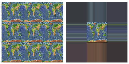
There is another pair of texture parameters to control how texture coordinates outside the range 0 to 1 are treated. As mentioned above, the default is to repeat the texture. The alternative is to “clamp” the texture. This means that when texture coordinates outside the range 0 to 1 are specified, those values are forced into that range: Values less than 0 are replaced by 0, and values greater than 1 are replaced by 1. Values can be clamped separately in the s and t directions using
glTexParameteri(GL_TEXTURE_2D, GL_TEXTURE_WRAP_S, GL_CLAMP);
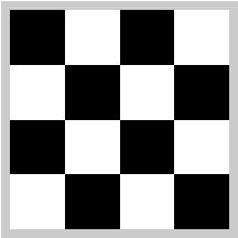
glTexParameteri(GL_TEXTURE_2D, GL_TEXTURE_WRAP_T, GL_CLAMP);Passing GL_REPEAT as the last parameter restores the default behavior. When clamping is in effect, texture coordinates outside the range 0 to 1 return the same color as a texel that lies along the outer edge of the image. Here is what the effect looks like on two textured squares:
The problem with linear filtering is that it will be very inefficient when a large texture is applied to a much smaller surface area. In this case, many texels map to one pixel, and computing the average of so many texels becomes very inefficient. There is a neat solution for this: mipmaps.
11.4.1 MipMaps
A mipmap for a texture is a scaled-down version of that texture. A complete set of mipmaps consists of the full-size texture, a half-size version in which each dimension is divided by two, a quarter-sized version, a one-eighth-sized version, and so on. If one dimension shrinks to a single pixel, it is not reduced further, but the other dimension will continue to be cut in half until it too reaches one pixel. In any case, the final mipmap consists of a single pixel. Here are the first few images in the set of mipmaps for a brick texture:
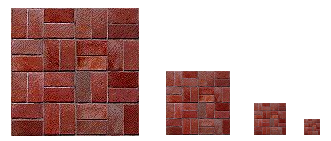
You’ll notice that the mipmaps become small very quickly. The total memory used by a set of mipmaps is only about one-third more than the memory used for the original texture, so the additional memory requirement is not a big issue when using mipmaps.
Mipmaps are used only for minification filtering. They are essentially a way of pre-computing the bulk of the averaging that is required when shrinking a texture to fit a surface. To texture a pixel, OpenGL can first select the mipmap whose texels most closely match the size of the pixel. It can then do linear filtering on that mipmap to compute a color, and it will have to average at most a few texels in order to do so.
11.5 Texture Mapping
Mapping a texture image to a surface is a fairly complex operation, since it requires more than just returning the color of the texel (pixel in a texture image) that contains some given texture coordinates.
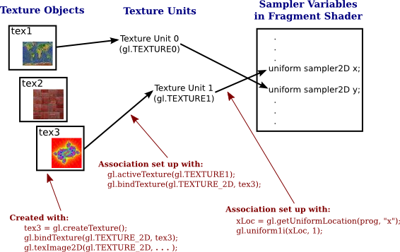
In order to do this we need a sampling process of computing a colour from an image texture and texture coordinates. A texture unit, also called a texture mapping unit (TMU) or a texture processing unit (TPU), is a hardware component in a GPU that does sampling.
- A texture object is a data structure that contains the color data for an image texture. The texture unit is the processor; the texture object holds the data that is processed. In GLSL, texture lookup is done using sampler variables.
- A sampler variable is a variable in a shader program. In GLSL ES 1.00, the only sampler types are sampler2D and samplerCube. A sampler2D is used to do lookup in a standard texture image; a samplerCube is used to do lookup in a cubemap texture. The value of a sampler variable is a reference to a texture unit. The value tells which texture unit is invoked when the sampler variable is used to do texture lookup.
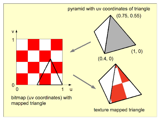
11.5.1 Texture Coordinates
Refers to the coordinate system on a texture image. Texture coordinates typically range from 0 to 1 both vertically and horizontally, with (0,0) at the lower left corner of the image. The term also refers to coordinates that are given for a surface and that are used to specify how a texture image should be mapped to the surface.
The texture coordinates of a vertex are an attribute of the vertex, just like color, normal vectors, and material properties. Texture coordinates are specified by the family of functions glTexCoord*, including the functions
- glTexCoord2f(s,t)
- glTexCoord2d(s,t)
- glTexCoord2fv(array)
- glTexCoord2dv(array)
For example, to apply the triangular region in the image shown below to the triangle in the xy-plane with vertices at (0,0), (0,1), and (1,0), we can say:
glNormal3d(0,0,1);       // This normal works for all three vertices.
glBegin(GL_TRIANGLES);
glTexCoord2d(0.3,0.1);   // Texture coords for vertex (0,0)
glVertex2d(0,0);
glTexCoord2d(0.45,0.6);  // Texture coords for vertex (0,1)
glVertex2d(0,1);
glTexCoord2d(0.25,0.7);  // Texture coords for vertex (1,0)
glVertex2d(1,0);
glEnd();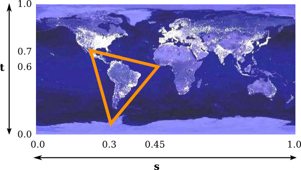
11.5.2 OpenGL Example
This code provides a basic structure. You’ll need to expand it by completing the array definitions, setting up buffers, handling user input, and managing window events. Additionally, integrate the transformation matrices for dynamic viewing and model transformation.
// Vertex Shader
const vertexShaderSource =
    "attribute vec2 a_coords;\n" +
    "attribute vec2 a_texCoords;\n" +
    "varying vec2 v_texCoords;\n" +
    "uniform mat4 model;\n" +
    "uniform mat4 view;\n" +
    "uniform mat4 projection;\n" +

    "void main() {\n" +
       "   v_texCoords = a_texCoords;\n" +
       "   gl_Position = projection * view * model * vec4(a_coords, 0.0, 1.0);\n" +
    "}\n";

// Fragment Shader
const fragmentShaderSource =
    "precision mediump float;\n" +
    "uniform sampler2D u_texture;\n" +  // A sampler variable to represent the texture.
    "varying vec2 v_texCoords;\n" +   // The texture coordinates for this pixel.
    "void main() {\n" +
    "   vec4 color = texture2D( u_texture, v_texCoords );\n" +  // Sample the texture.
    "   gl_FragColor = color;\n" +   // Just use the color from the texture as the pixel color.
    "}\n";
11.6 Texture Transformations
Since texture coordinates are no different from vertex coordinates, they can be transformed in exactly the same way. OpenGL maintains a texture transformation as part of its state, along with the modelview and projection transformations. The current value of each of the three transformations is stored as a matrix. When a texture is applied to an object, the texture coordinates that were specified for its vertices are transformed by the texture matrix. The transformed texture coordinates are then used to pick out a point in the texture.
The texture matrix can represent scaling, rotation, translation and combinations of these basic transforms. To specify a texture transform, you have to use glMatrixMode() to set the matrix mode to GL_TEXTURE. With this mode in effect, calls to methods such as glRotate*, glScale*, and glLoadIdentity are applied to the texture matrix. For example to install a texture transform that scales texture coordinates by a factor of two in each direction, you could say:
11.7 Applying Textures to Shaders
By applying textures to shaders, we can create rich, detailed visuals that bring virtual environments to life.
11.7.1 Normal(Bump) Mapping
Normal maps are a type of Bump Map. They are a special kind of texture that allow you to add surface detail such as bumps, grooves, and scratches to a model which catch the light as if they are represented by real geometry.
For example, you might want to show a surface which has grooves and screws or rivets across the surface, like an aircraft hull. One way to do this would be to model these details as geometry, as shown below.
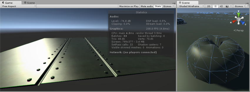
Depending on the situation it is not normally a good idea to have such tiny details modelled as “real” geometry. On the right you can see the polygons required to make up the detail of a single screwhead. Over a large model with lots of fine surface detail this would require a very high number of polygons to be drawn. To avoid this, we should use a normal map to represent the fine surface detail, and a lower resolution polygonal surface for the larger shape of the model.
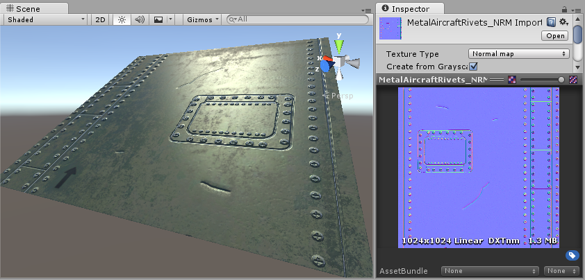
If we instead represent this detail with a bump map, the surface geometry can become much simpler, and the detail is represented as a texture which modulates how light reflects off the surface. This is something modern graphics hardware can do extremely fast. Your metal surface can now be a low-poly flat plane, and the screws, rivets, grooves and scratches will catch the light and appear to have depth because of the texture.
Using this basic smooth shading, the data determining the normal direction is actually only stored per vertex, so the changing values across the surface are interpolated from one vertex to the next. In the diagram below, the red arrows indicate the stored normal direction at each vertex, and the orange arrows indicate examples of the interpolated normal directions across the area of the polygon.

Normal mapping takes this modification of surface normals one step further, by using a texture to store information about how to modify the surface normals across the model. A normal map is an image texture mapped to the surface of a model, similar to regular colour textures, however each pixel in the texture of the normal map (called a texel) represents a deviation in surface normal direction away from the “true” surface normal of the flat (or smooth interpolated) polygon.

The colours visible in a raw normal map file typically have a blueish hue, and don’t contain any actual light or dark shading - this is because the colours themselves are not intended to be displayed as they are.
Instead, the RGB values of each texel represent the X,Y & Z values of a direction vector, and are applied as a modification to the basic interpolated smooth normals of the polygon surfaces.
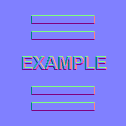
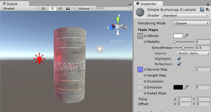
This is a simple normal map, containing the bump information for some raised rectangles and text. This normal map can be imported into Unity and placed into Normal Map slot of the Standard Shader. When combined in a material with a colour map (the Albedo map) and applied to the surface of of the cylinder mesh above, the result looks like this:
11.7.2 Height Mapping
A heightmap can be used in bump mapping to calculate where this 3D data would create shadow in a material. This means that while surface bumps will appear to protrude and occlude each other, the “silhouette” of the model will never be modified, because ultimately the effect is drawn onto the surface of the model and does not modify the actual geometry.
However, it can also be used in displacement mapping to displace the actual geometric position of points over the textured surface
Finally it can also be used for terrain where the heightmap is converted into a 3D mesh.
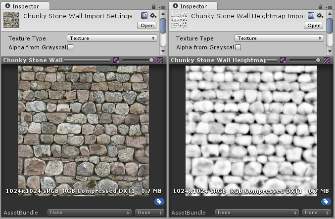
A heightmap should be a greyscale image, with white areas representing the high areas of your texture and black representing the low areas. Here’s a typical albedo map and a heightmap to match.
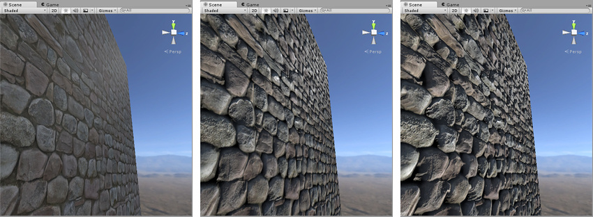
From left to right in the above image: 1. A rocky wall material with albedo assigned, but no normalmap or heightmap. 2. The normal assigned. Lighting is modified on the surface, but rocks do not occlude each other. 3. The final effect with normalmap and heightmap assigned. The rocks appear to protrude out from the surface, and nearer rocks seem to occlude rocks behind them.
11.7.3 Occlusion Mapping
The occlusion map is used to provide information about which areas of the model should receive high or low indirect lighting. Indirect lighting comes from ambient lighting and reflections, and so steep concave parts of your model such as a crack or fold would not realistically receive much indirect light.
Occlusion texture maps are normally calculated by 3D applications directly from the 3D model using the modeller or third party software.
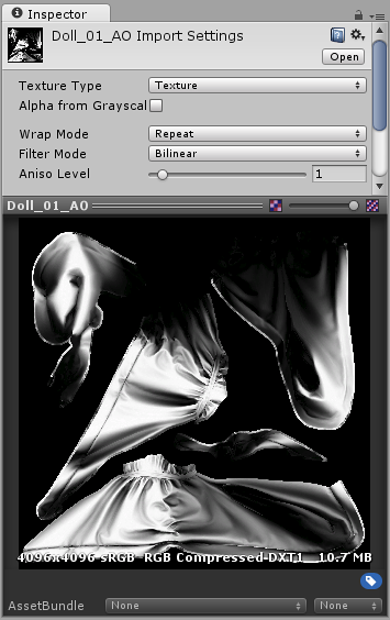
An occlusion map is a greyscale image, with white indicating areas that should receive full indirect lighting, and black indicating no indirect lighting. Sometimes this is as simple as a greyscale heightmap, for simple surfaces (such as the knobbly stone wall texture shown in the heightmap example above).
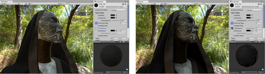
Before and after applying an occlusion map. The areas that are partially obscured, particularly in the folds of fabric around the neck, are lit too brightly on the left. After the ambient occlusion map is assigned, these areas are no longer lit by the green ambient light from the surrounding wooded environment.
11.7.4 Secondary Mapping
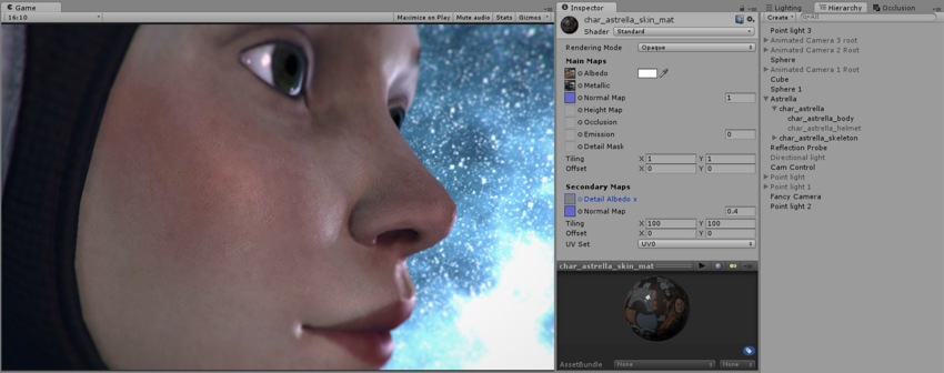
Secondary Maps (or Detail maps) allow you to overlay a second set of textures on top of the main textures listed above. You can apply a second Albedo colour map, and a second Normal map. Typically, these would be mapped on a much smaller scale repeated many times across the object’s surface, compared with the main Albedo and Detail maps.
The reason for this is to allow the material to have sharp detail when viewed up close, while also having a normal level of detail when viewed from further away, without having to use a single extremely high texture map to achieve both goals.
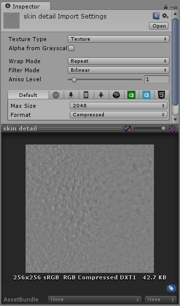
Typical uses for detail textures would be: - Adding skin detail, such as pores and hairs, to a character’s skin - Adding tiny cracks and lichen growth to a brick wall - adding small scratches and scuffs to a large metal container
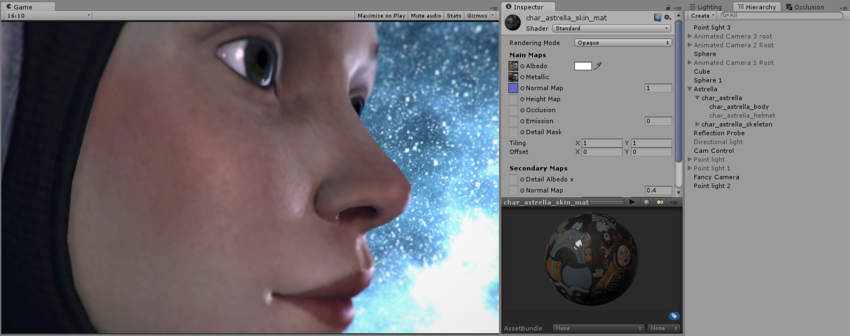
The Albedo skin pore detail texture:
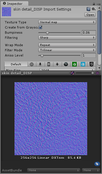
The normal map for the skin pore detail:
The end result, the character now has subtle skin pore detail across her skin, at a much higher resolution than the base Albedo or Normal map layer would have allowed.
11.8 Cool Things we can also do
Up until now, all of our textures have been image textures. With an image texture, a color is computed by sampling the image, based on a pair of texture coordinates. The image essentially defines a function that takes texture coordinates as input and returns a color as output. However, there are other ways to define such functions besides looking up values in an image.
11.8.1 Procedurally Generated Textures
A texture for which the value at a given set of texture coordinates is computed as a mathematical function of the coordinates, as opposed to an image texture where the value is obtained by sampling an image.


The idea is simple: Take a vec2 representing a set of texture coordinates. Then, instead of using a sampler2D to look up a color, use the vec2 as input to some mathematical computation that computes a vec4 representing a color. In theory any computation could be used, as long as the components of the vec4 are in the range 0.0 to 1.0.
There are many different types of approaches for generating procedural textures.

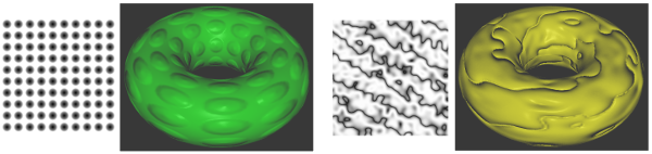
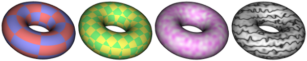
The torus on the left uses a 2D procedural texture representing a checkerboard pattern.
The 2D texture coordinates were provided, as usual, as values of a vertex attribute variable in the shader program. The checkerboard pattern is regular grid of equal-sized colored squares, but, as with any 2D texture, the pattern is stretched and distorted when it is mapped to the curved surface of the torus. Given texture coordinates in the varying variable v_texCoords, the color value for the checkerboard texture can be computed as follows in the fragment shader:
vec4 color;
float a = floor(v_texCoords.x * scale);
float b = floor(v_texCoords.y * scale);
if (mod(a+b, 2.0) > 0.5) {  // a+b is odd
    color = vec3(1.0, 0.5, 0.5, 1.0); // pink
}
else {  // a+b is even
    color = vec3(0.6, 0.6, 1.0, 1.0); // light blue
}
The scale in the second and third lines represents a texture transformation that is used to adapt the size of the texture to the object that is being textured. (The texture coordinates for the torus range from 0 to 1; without the scaling, only one square in the checkerboard pattern would be mapped to the torus. For the torus in the picture, scale is 8.) The floor function computes the largest integer less than or equal to its parameter, so a and b are integers. The value of mod(a+b,2.0) is either 0.0 or 1.0, so the test in the fourth line tests whether a+b is even or odd. The idea here is that when either a or b increases or decreases by 1, a+b will change from even to odd or from odd to even; that ensures that neighboring squares in the pattern will be differently colored.
11.8.2 Loading Textures from a Buffer
Texture images for use in an OpenGL program usually come from an external source, most often an image file. However, OpenGL is itself a powerful engine for creating images. Sometimes, instead of loading an image file, it’s convenient to have OpenGL create the image internally, by rendering it.
This is possible because OpenGL can read texture data from its own color buffer, where it does its drawing. To create a texture image using OpenGL, you just have to draw the image using standard OpenGL drawing commands and then load that image as a texture using the method
In this method,
-
targetwill beGL_TEXTURE_2D; -
mipmapLevelshould be 0; - the
internalFormatwill ordinarily beGL_RGBorGL_RGBA; -
xandyspecify the lower left corner of the rectangle from which the texture will be read; -
widthandheightare the size of that rectangle; -
bordershould be 0.
As usual with textures, the width and height should ordinarily be powers of two. A call to glCopyTexImage2D will typically look like:
The end result is that the specified rectangle from the color buffer will be copied to texture memory and will become the current 2D texture. This works in the same way as a call to glTexImage2D(), except for the source of the image data.
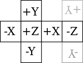
11.8.3 CubeMaps
- Cube mapping is a technique used to simulate reflective surfaces or dynamic environment effects on objects, particularly for things like mirrors, shiny surfaces, or objects that need to reflect their surroundings.
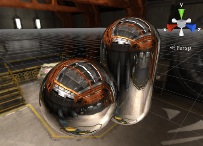
- It works by rendering six textures—one for each face of a cube—around a specific point in 3D space. These six textures are then combined to create a seamless environment map.
- When applied to a 3D object (like a sphere or a car), the cube map simulates how the object reflects its environment by using this cube-shaped texture.
- Applications: Commonly used in reflections, refractions, and in rendering things like water or metallic surfaces, where realistic environmental reflections are needed.
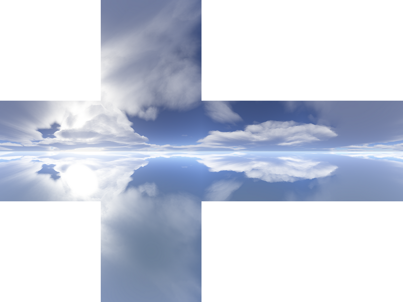
11.8.4 SkyBoxes
- A skybox is a method for creating the illusion of a large, distant environment, such as a sky, horizon, or surrounding scenery. It is used in 3D games and simulations to give the player the impression that they are in a vast world, while in reality, they are in a relatively small area.
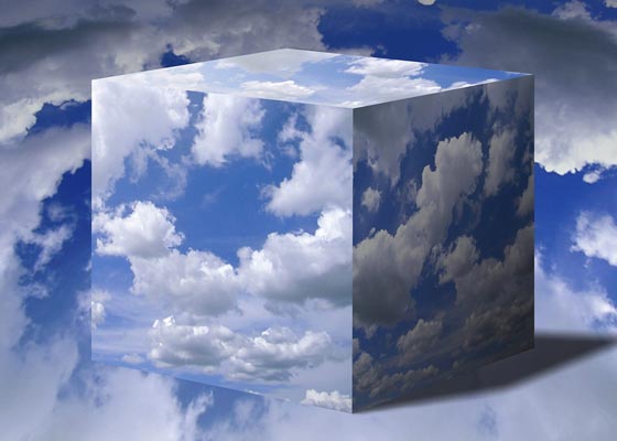
- A skybox typically consists of six images or textures mapped onto the inner faces of a large cube that surrounds the player or camera. These images are aligned so that they give the impression of a continuous 360° environment.
- Unlike cube mapping, which can be dynamic and reactive to an object’s movement or position, the skybox is static, providing a consistent backdrop to the entire scene.
- Applications: Skyboxes are commonly used to render things like the sky, distant mountains, and other scenery that should appear far away from the player.