8 OpenGL
8.1 Introduction

OpenGL (Open Graphics Library introduced in 1992) is a cross-language, cross-platform API for rendering 2D and 3D vector graphics. It is widely used in CAD, virtual reality, video games, and flight simulation. The API is typically used to interact with a Graphics Processing Unit (GPU), to achieve hardware-accelerated rendering.
OpenGL is the basis for WebGL, the current standard for 3D applications on the Web.
8.2 GLUT
GLUT (OpenGL Utility Toolkit) is a library of utilities for OpenGL programs, which provides functions for creating windows, handling user input, and managing the main loop.
    glutInit(&argc, argv);
    glutInitDisplayMode(GLUT_DOUBLE | GLUT_RGB | GLUT_DEPTH);
    glutInitWindowSize(800, 600);
    glutCreateWindow("Orbiting Lights and Cylinder Visualization");

    glClearColor(0.0, 0.0, 0.0, 1.0);
    init();

    glutDisplayFunc(display);
    glutReshapeFunc(reshape);
    glutIdleFunc(idle);

    glutMainLoop();
These functions are part of an OpenGL program using the GLUT (OpenGL Utility Toolkit) library to create a window and render graphics. Here’s a breakdown of what each function does:
glutInit(&argc, argv);
This function initializes the GLUT library. It takes theargcandargvarguments from the command line, which are passed to themain()function of a C/C++ program.glutInitprocesses any command-line options that control GLUT’s behavior, such as display mode settings.-
glutInitDisplayMode(GLUT_DOUBLE | GLUT_RGB | GLUT_DEPTH);
This function sets the initial display mode for the window. The parameters passed here are:-
GLUT_DOUBLE: Enables double buffering, where rendering is done on a back buffer, and then it is swapped with the front buffer to display. This prevents flickering during rendering. -
GLUT_RGB: Specifies that the window will use an RGB color model. -
GLUT_DEPTH: Enables depth buffering, which is used to handle depth calculations and ensure that objects are rendered in the correct order (near objects obscure far objects).
-
glutInitWindowSize(800, 600);
This function sets the initial size of the window to 800 pixels wide and 600 pixels tall.glutCreateWindow("Orbiting Lights and Cylinder Visualization");
This function creates a window with the title “Orbiting Lights and Cylinder Visualization”. It returns an integer identifier for the window, though in this case, the return value is not stored.glClearColor(0.0, 0.0, 0.0, 1.0);
This function sets the clear color for the window, which is the color used when the color buffers are cleared. The values(0.0, 0.0, 0.0, 1.0)correspond to black with full opacity (RGBA).init();
This is a custom function that you would define elsewhere in your program. Typically,init()is used to set up any additional OpenGL states or initialize objects that need to be drawn.glutDisplayFunc(display);
This function registers the display callback function,display, which will be called whenever the window needs to be redrawn. Thedisplayfunction contains the code for rendering the scene.glutReshapeFunc(reshape);
This function registers the reshape callback function,reshape, which is called whenever the window is resized. Thereshapefunction typically adjusts the viewport and projection matrix to ensure the scene is rendered correctly in the new window size.glutIdleFunc(idle);
This function registers the idle callback function,idle, which is called whenever the application is idle (not handling other events). Theidlefunction can be used to update animations or perform background tasks.glutMainLoop();
This function enters the GLUT event processing loop. It listens for events such as keyboard input, mouse movement, and window resizing, and dispatches them to the appropriate callback functions. The program will remain in this loop until the window is closed or the program is terminated.
These functions together initialize a window, set up rendering properties, and enter the main loop where the program will continuously render graphics and respond to user input.
8.3 Shapes and Colours in OpenGL
8.3.1 Primitives
In OpenGL, the basic geometric shapes are called primitives. These include points, lines, and triangles, which are used as the building blocks for creating complex 3D scenes. A vertex is simply a point in 3D, given by its x, y, and z coordinates.
- Points: Single vertices.
- Lines: Connecting two vertices.
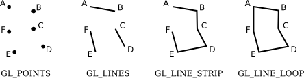
- Triangles: A polygon with three vertices.
- Obsolete: Primitives which are no longer supported
Example:
glBegin(GL_TRIANGLES);
glVertex2f( -0.7, -0.5 );
glVertex2f( 0.7, -0.5 );
glVertex2f( 0, 0.7 );
glEnd();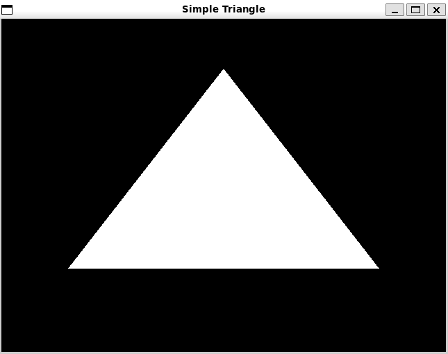
Each vertex of the triangle is specified by a call to the function glVertex2f. Vertices must be specified between calls to glBegin and glEnd. The parameter to glBegin tells which type of primitive is being drawn. The GL_TRIANGLES primitive allows you to draw more than one triangle: Just specify three vertices for each triangle that you want to draw.
The simplest primitive is GL_POINTS, which simply renders a point at each vertex of the primitive. By default, a point is rendered as a single pixel. The size of point primitives can be changed by calling
where the parameter, size, is of type float and specifies the diameter of the rendered point, in pixels. By default, points are squares. You can get circular points by calling
The functions glPointSize and glEnable change the OpenGL “state.” The state includes all the settings that affect rendering. The functions glEnable and glDisable can be used to turn many features on and off. In general, the rule is that any rendering feature that requires extra computation is turned off by default. If you want that feature, you have to turn it on by calling glEnable with the appropriate parameter.
There are three primitives for drawing line segments: GL_LINES, GL_LINE_STRIP, and GL_LINE_LOOP.
- GL_LINES draws disconnected line segments; specify two vertices for each segment that you want to draw.
- GL_LINE_STRIP draws connected sequences of line segments.
- GL_LINE_LOOP adds an extra line segment from the final vertex back to the first vertex.
The width for line primitives can be set by calling glLineWidth(width).
The line width is always specified in pixels.
It is not subject to scaling by transformations.
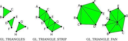
There are three primitives for drawing triangles segments: GL_TRIANGLES, GL_TRIANGLE_STRIP AND GL_TRIANGLE_FAN
- GL_TRIANGLES primitive, with nine vertices. With that primitive, every set of three vertices makes a separate triangle.
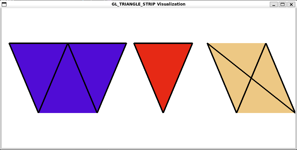
- GL_TRIANGLE_STRIP primitive, the first three vertices produce a triangle. After that, every new vertex adds another triangle to the strip, connecting the new vertex to the two previous vertices.
- GL_TRIANGLE_FAN, the first three vertices make a triangle, and every vertex after that adds anther triangle, but in this case, the new triangle is made by connecting the new vertex to the previous vertex and to the very first vertex that was specified (vertex “A” in the picture).
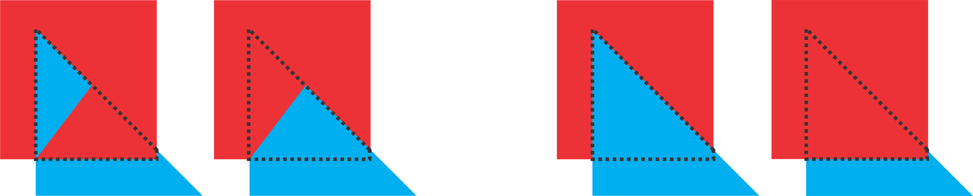
The figure below demonstrates how GL_TRIANGLE_STRIP functions.
The first shape is generated by passing 5 vertices into the method as follows :
// Draw the first shape with more vertices (Triangle Strip)
    glBegin(GL_TRIANGLE_STRIP);
        glVertex2f(-0.8f,  0.5f);  // Vertex 1
        glVertex2f(-0.6f, -0.5f);  // Vertex 2
        glVertex2f(-0.4f,  0.5f);  // Vertex 3
        glVertex2f(-0.2f, -0.5f);  // Vertex 4
        glVertex2f( 0.0f,  0.5f);  // Vertex 5
    glEnd();
The 2nd and third shapes are the results if we only fed 3 and 4 vertices, respectively. I have added outlines so that you can visualise the individual triangles that are rendered for each set of three vertices.
8.3.2 Colour
Colour in OpenGL is typically specified using RGBA (Red, Green, Blue, Alpha) values. Alpha represents the transparency of the colour.
If you would like to use integer color values in the range 0 to 255, you can use glColor3ub() or glColor4ub to set the color. In these function names, “ub” stands for “unsigned byte.” Unsigned byte is an eight-bit data type with values in the range 0 to 255. Here are some examples of commands for setting drawing colors in OpenGL:
glColor3f(0,0,0);         // Draw in black.

glColor3f(1,1,1);         // Draw in white.

glColor3f(1,0,0);         // Draw in full-intensity red.

glColor3ub(1,0,0);        // Draw in a color just a tiny bit different from
                          // black.  (The suffix, "ub" or "f", is important!)

glColor3ub(255,0,0);      // Draw in full-intensity red.

glColor4f(1, 0, 0, 0.5);  // Draw in transparent red, but only if OpenGL
                          // has been configured to do transparency.  By
                          // default this is the same as drawing in plain red.
Using any of these functions sets the value of a “current color,” which is part of the OpenGL state. When you generate a vertex with one of the glVertex* functions, the current color is saved along with the vertex coordinates, as an attribute of the vertex. Using any of these functions sets the value of a “current color,” which is part of the OpenGL state. When you generate a vertex with one of the glVertex* functions, the current color is saved along with the vertex coordinates, as an attribute of the vertex.
8.3.3 Using Arrays
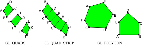
Vertex and color data can be efficiently managed using arrays. This allows for better performance, especially when dealing with large numbers of vertices. As an example, suppose that we want to draw a square. We need two coordinates for each vertex of the square. In C, we can put all 8 coordinates into one array and use glVertex2fv to pull out the coordinates that we need:
float coords[] = { -0.5, -0.5,  0.5, -0.5,  0.5, 0.5,  -0.5, 0.5 };

glBegin(GL_TRIANGLE_FAN);
glVertex2fv(coords);      // Uses coords[0] and coords[1].
glVertex2fv(coords + 2);  // Uses coords[2] and coords[3].
glVertex2fv(coords + 4);  // Uses coords[4] and coords[5].
glVertex2fv(coords + 6);  // Uses coords[6] and coords[7].
glEnd();
This example uses “pointer arithmetic” in which coords + N represents a pointer to the N-th element of the array.
8.3.5 Clearing the scene
Clearing the screen before drawing a new frame is crucial to remove artifacts from the previous frame. A common operation is to clear the drawing area by filling it with some background color. It is be possible to do that by drawing a big colored rectangle, but OpenGL has a potentially more efficient way to do it. The function
This function sets up a color to be used for clearing the drawing area.
Then in order to actually clear the screen we use the glClear function.
It takes as input a Buffer, which is the region in memory where the related information is stored.
GL_COLOR_BUFFER_BIT referencing where in memory the colour information is stored for each pixel.
GL_DEPTH_BUFFER_BIT referencing where in memory the depth information is stored for each pixel.
8.4 Occlusion
A process whereby something is hidden or obscured from prominence or view.
An obvious point about viewing in 3D is that one object can be behind another object. When this happens, the back object is hidden from the viewer by the front object. When we create an image of a 3D world, we have to make sure that objects that are supposed to be hidden behind other objects are in fact not visible in the image. This is the hidden surface problem.
The solution might seem simple enough: Just draw the objects in order from back to front. If one object is behind another, the back object will be covered up later when the front object is drawn. This is called the painter’s algorithm.
In particular, when using OpenGL it draws the objects in the order the commands are called.
void display() {
    glClear(GL_COLOR_BUFFER_BIT);

    // Left side: Square overlapping a Triangle
    // Draw Triangle
    glBegin(GL_TRIANGLES);
        glColor3f(1.0, 0.0, 0.0); // Red color
        glVertex2i(50, 150);
        glVertex2i(150, 150);
        glVertex2i(100, 250);
    glEnd();

    // Draw Square
    glBegin(GL_QUADS);
        glColor3f(0.0, 0.0, 1.0); // Blue color
        glVertex2i(70, 170);
        glVertex2i(170, 170);
        glVertex2i(170, 270);
        glVertex2i(70, 270);
    glEnd();

    // Right side: Triangle overlapping a Square
    // Draw Square
    glBegin(GL_QUADS);
        glColor3f(0.0, 1.0, 0.0); // Green color
        glVertex2i(230, 150);
        glVertex2i(330, 150);
        glVertex2i(330, 250);
        glVertex2i(230, 250);
    glEnd();

    // Draw Triangle
    glBegin(GL_TRIANGLES);
        glColor3f(1.0, 1.0, 0.0); // Yellow color
        glVertex2i(250, 170);
        glVertex2i(350, 170);
        glVertex2i(300, 270);
    glEnd();

    glFlush();
}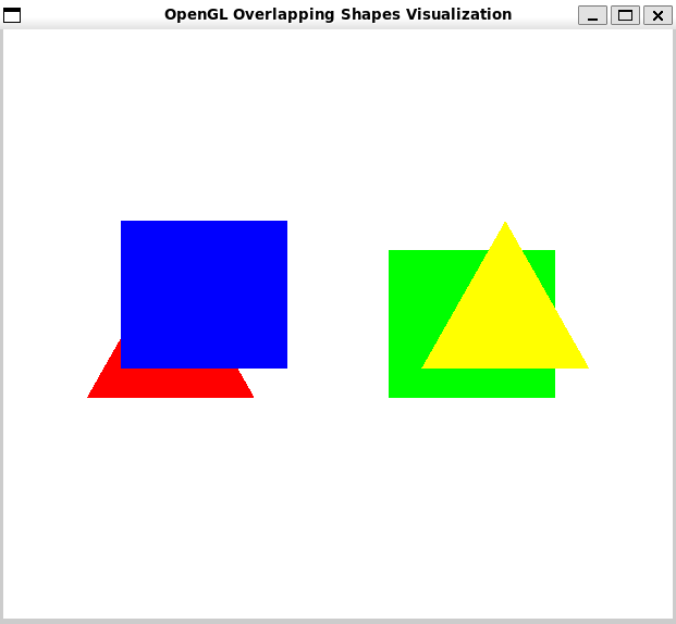
However this introduces some limitations, you can have objects that intersect, so that part of each object is hidden by the other. Whatever order you draw the objects in, there will be some points where the wrong object is visible.

To fix this, you would have to cut the objects into pieces, along the intersection, and treat the pieces as separate objects.
In fact, there can be problems even if there are no intersecting objects: It’s possible to have three non-intersecting objects where the first object hides part of the second, the second hides part of the third, and the third hides part of the first.
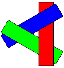
The painter’s algorithm will fail regardless of the order in which the three objects are drawn. The solution again is to cut the objects into pieces, but now it’s not so obvious where to cut.
Even though these problems can be solved, there is another issue. The correct drawing order can change when the point of view is changed or when a geometric transformation is applied, which means that the correct drawing order has to be recomputed every time that happens. In an animation, that would mean for every frame.
8.4.1 Depth Test
So, OpenGL does not use the painter’s algorithm. Instead, it uses a technique called the depth test. The depth test solves the hidden surface problem no matter what order the objects are drawn in, so you can draw them in any order you want! The term “depth” here has to do with the distance from the viewer to the object.
Objects at greater depth are farther from the viewer. An object with smaller depth will hide an object with greater depth. To implement the depth test algorithm, OpenGL stores a depth value for each pixel in the image. The extra memory that is used to store these depth values makes up the depth buffer that I mentioned earlier.
The depth test, also known as z-buffering or depth buffering, is a computer graphics technique used to determine which objects, or parts of objects, are visible in a scene. It helps render a 3D scene onto a 2D screen by ensuring that only the surfaces of objects closest to the viewer are displayed. Here’s how it works:
-
Depth Buffer Initialization:
- A depth buffer (or z-buffer) is created, which has the same dimensions as the display screen. Each element in this buffer corresponds to a pixel on the screen and holds a depth value (z-value).
-
Rendering Process:
- When a 3D scene is rendered, each pixel’s depth is calculated as it is projected onto the 2D screen.
- For each pixel to be drawn, the depth value is compared with the current value stored in the depth buffer at the corresponding position.
-
Depth Comparison:
If the calculated depth value of the current pixel is less than the value stored in the depth buffer (meaning it is closer to the viewer), the depth buffer is updated with the new depth value, and the pixel is drawn.
If the calculated depth value is greater than or equal to the value in the depth buffer, the pixel is discarded (not drawn), as it is behind another object already rendered.
-
Result:
- This process ensures that only the nearest surfaces are rendered, creating a correct representation of the 3D scene with proper occlusions.
8.4.1.1 Example
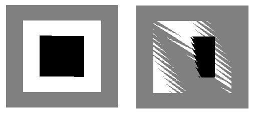
Lets consider drawing the following image. We can draw the shapes in any order, in this case we chose to draw the square, then the triangle and finally the pentagon.
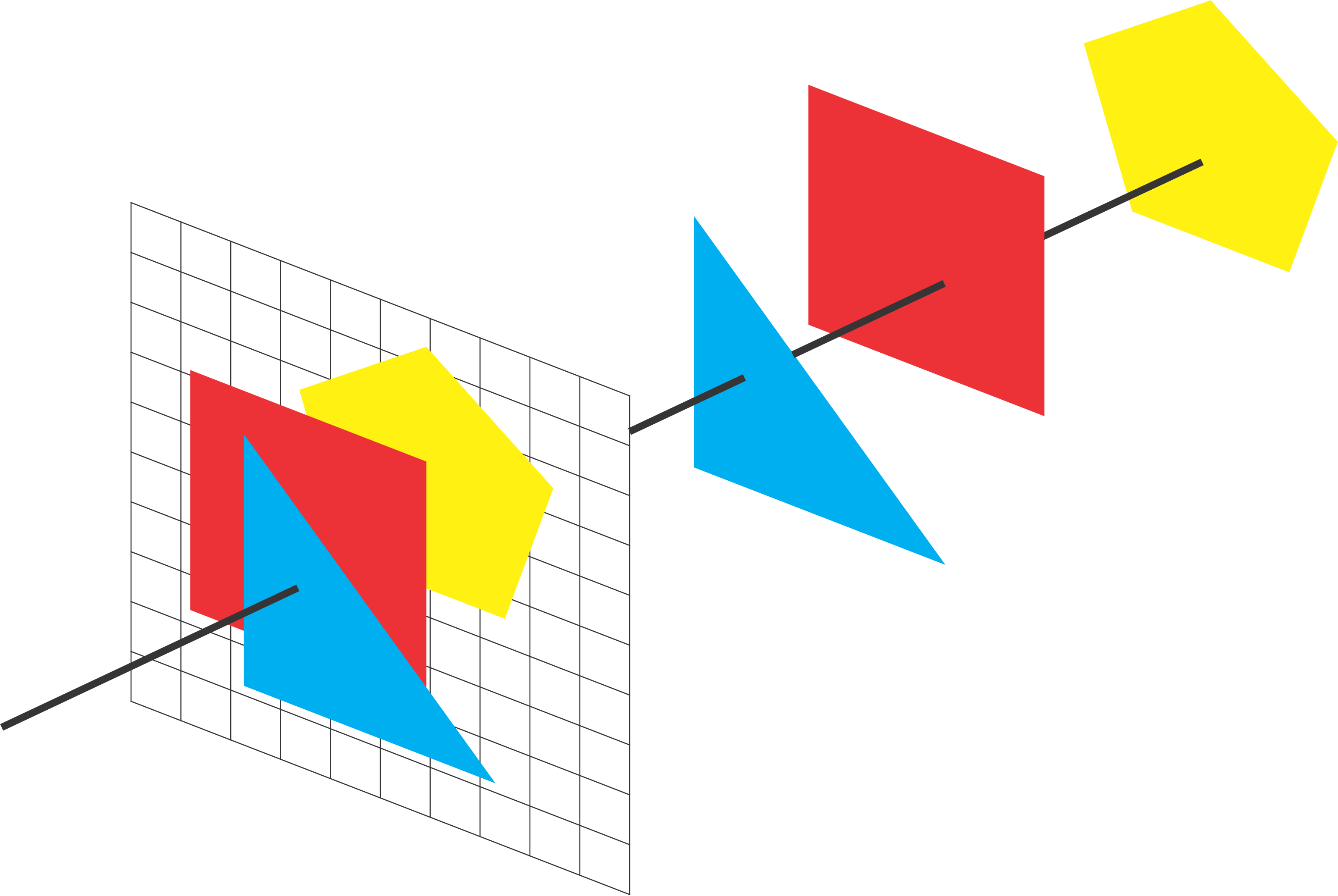
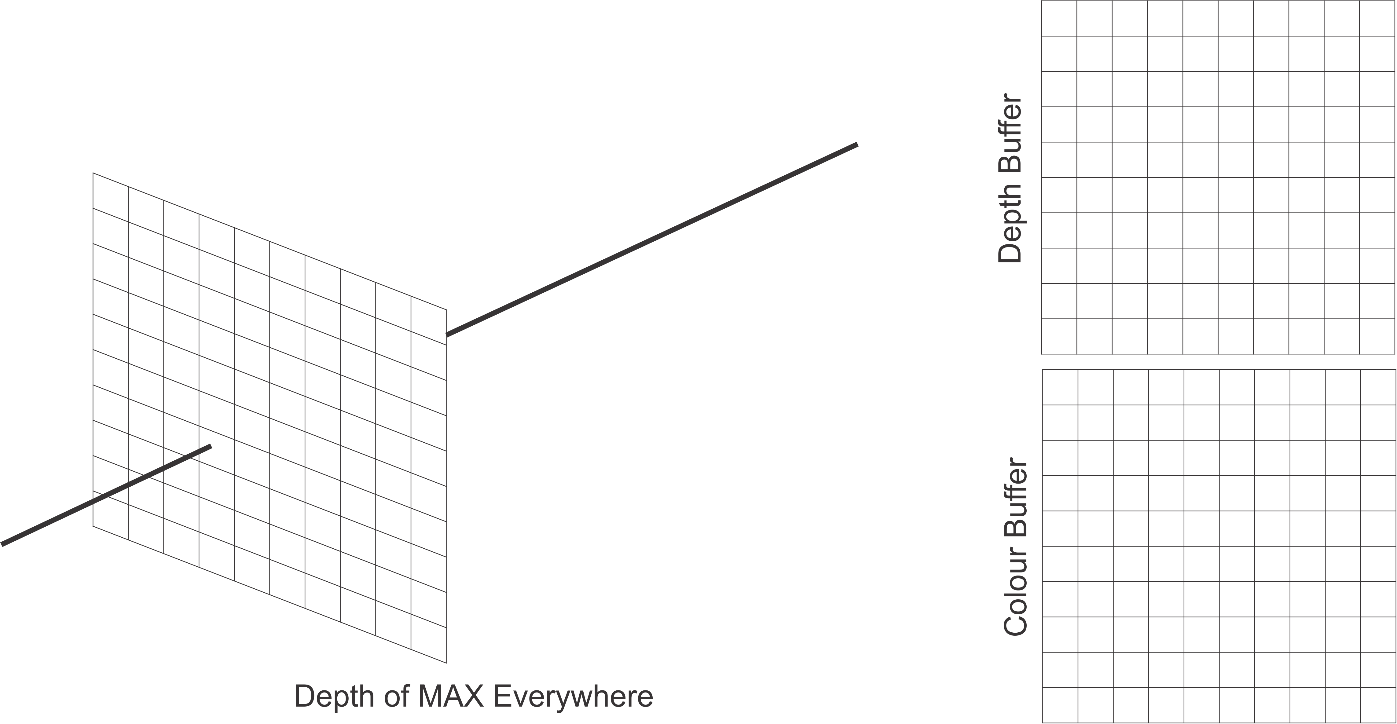
Initialise the depth and colour buffers before rendering. Note each element in the depth buffer is initialised to a max value.
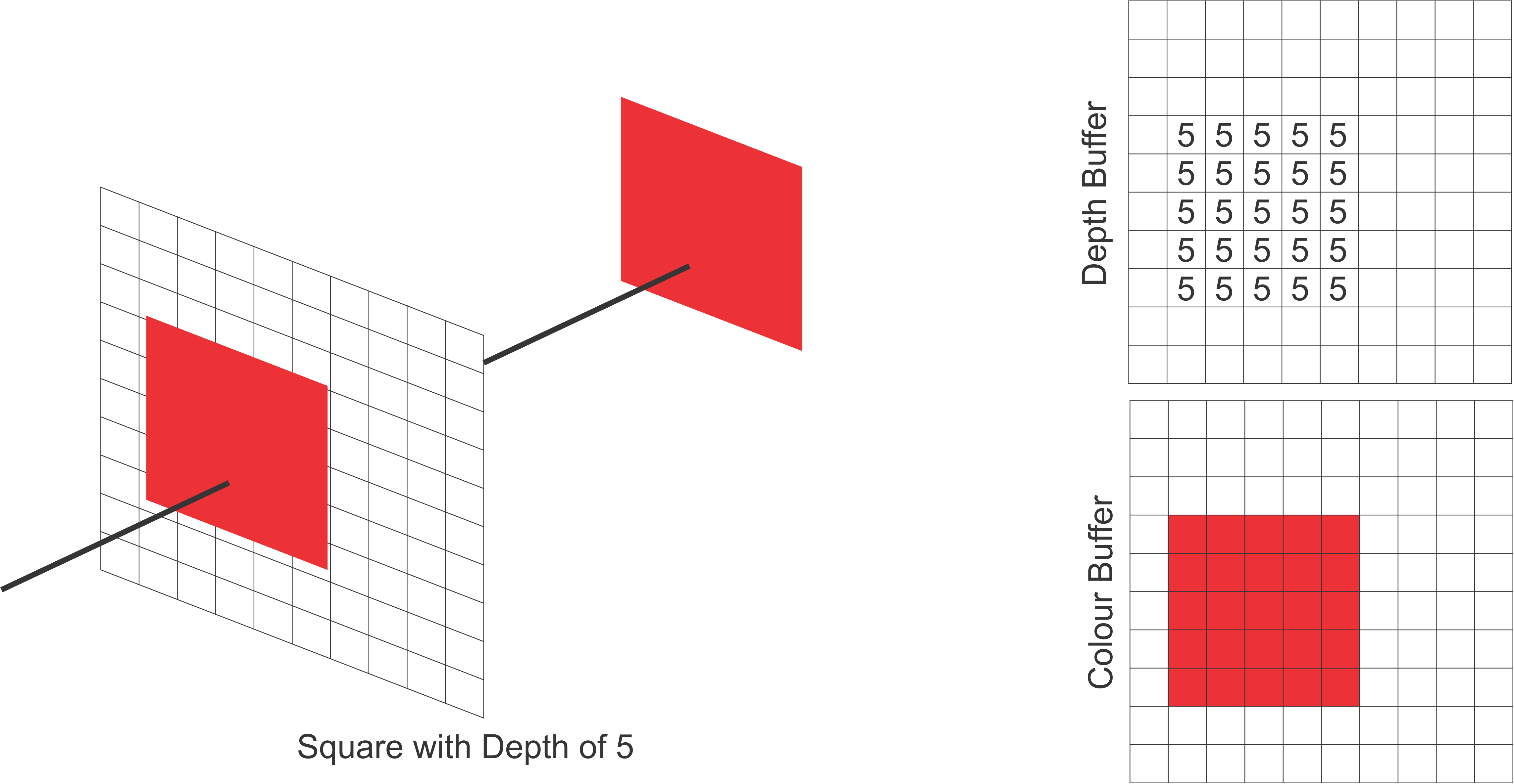
For each pixel coordinate in our scene we compare the depth of the square (depth of 5) at that point with the corresponding depth buffer value. For each depth value less than the current we update the depth buffer. Since this is the first object being processed, each coordinate of square will be less than the depth buffer values and therefore every point will be reflected in the colour buffer.
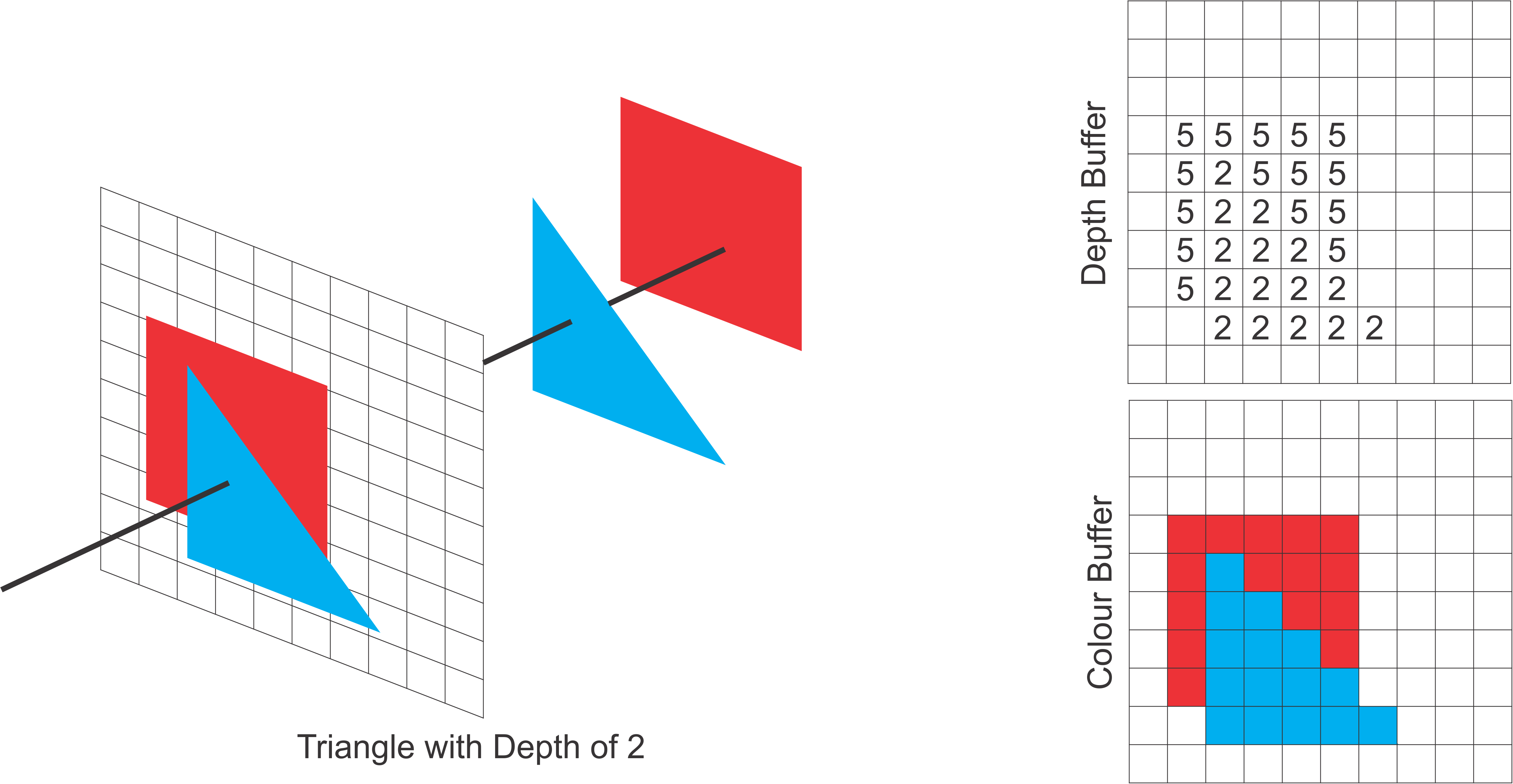
Next we compare the depth values of the triangle (depth of 2).
Since these are less than those of the square and the default max value, we update accordingly.
If 2 is less than the current depth value we also update the colour buffer with blue.
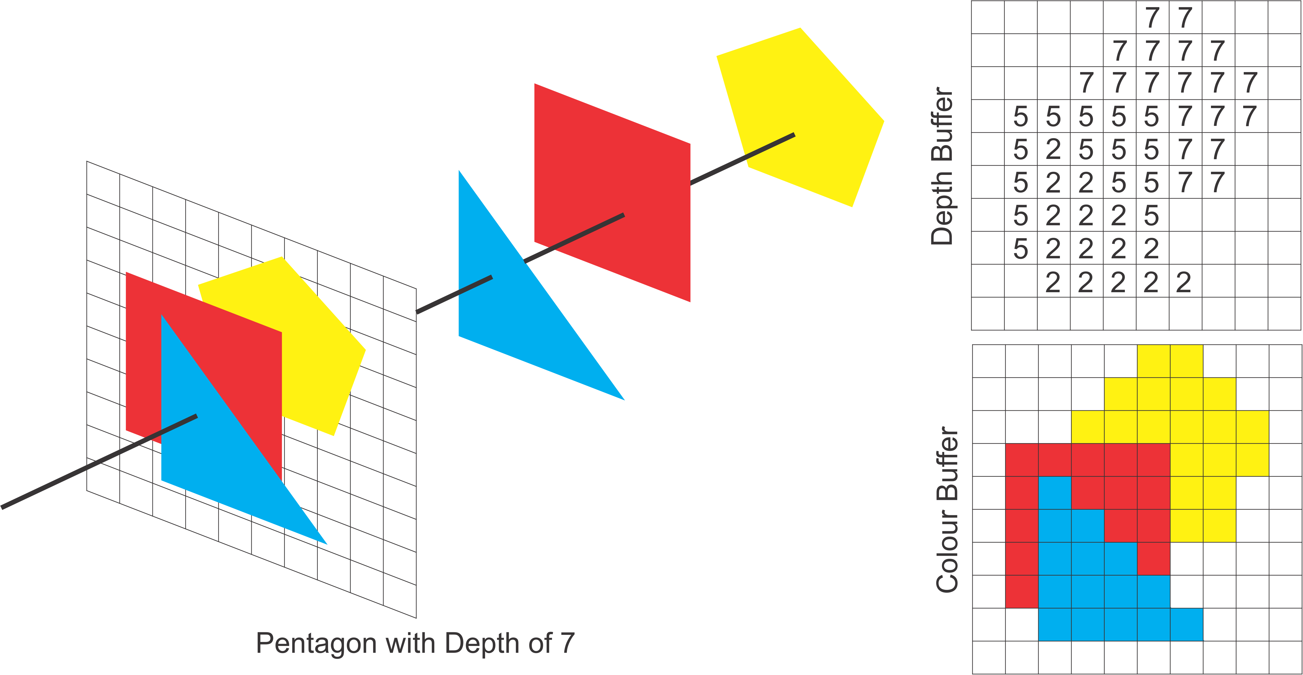
Lastly we draw the pentagon. Once again for pixel associated with the pentagon we will compare its depth (depth of 7). In the case where the depth buffer was less than 7 for example for some pixels of the square, we do not update the buffers.
By default, the depth test is not turned on, which can lead to very bad results when drawing in 3D. You can enable the depth test by calling
There is another issue with the depth buffer algorithm. It can give some strange results when two objects have exactly the same depth value. Logically, it’s not even clear which object should be visible, but the real problem with the depth test is that it might show one object at some points and the second object at some other points. This is possible because numerical calculations are not perfectly accurate. Here an actual example of this Z-fighting:
To fix Z-fighting:
Increase Depth Buffer Precision:
- Use a depth buffer with more bits, such as a 24-bit or 32-bit depth buffer instead of a 16-bit depth buffer. This can provide finer granularity for depth comparisons.
// Request a depth buffer with higher precision in your OpenGL context
glutInitDisplayMode(GLUT_DEPTH | GLUT_DOUBLE | GLUT_RGBA);
Adjust the Near and Far Planes:
- Move the near plane as far away as possible and the far plane as close as possible. This reduces the range of depth values, allowing the depth buffer to use its precision more effectively.
// Example: Setting near and far planes in the perspective matrix
gluPerspective(fov, aspectRatio, nearPlane, farPlane);
// nearPlane should be as large as possible
// farPlane should be as small as possible
Polygon Offset:
- Use the glPolygonOffset function to add an offset to the depth values of polygons. This is particularly useful for rendering coplanar surfaces, such as decals or shadows.
// Enable polygon offset fill
glEnable(GL_POLYGON_OFFSET_FILL);
// Set the factor and units for the polygon offset
glPolygonOffset(factor, units);
The factor and units parameters control the scale and bias of the offset, respectively.
Adjust these values based on the specific requirements of your scene.
8.4.2 Occlusion Culling
Occlusion culling is a rendering optimization technique used in computer graphics to improve performance by not rendering objects that are completely hidden (occluded) by other objects in the scene. This technique ensures that only visible objects are processed by the graphics pipeline, reducing the workload on the GPU and potentially increasing frame rates.
8.5 OpenGL in 3D
In three dimensions, you need three numbers to specify a point. (That’s essentially what it means to be three dimensional.) The third coordinate is often called z. The z-axis is perpendicular to both the x-axis and the y-axis.
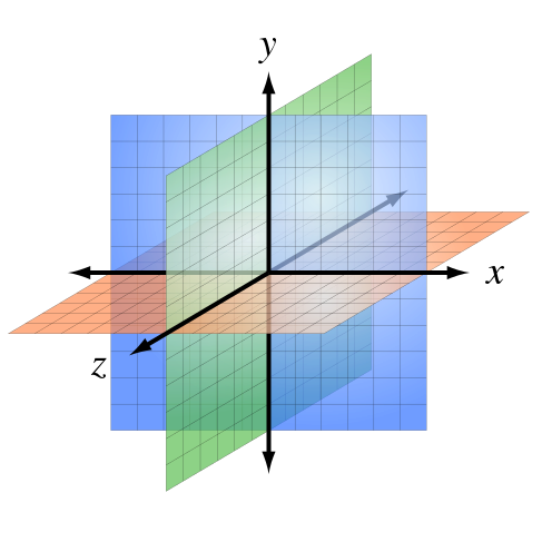
OpenGL programmers usually think in terms of a coordinate system in which the x- and y-axes lie in the plane of the screen, and the z-axis is perpendicular to the screen with positive direction pointing into the screen.
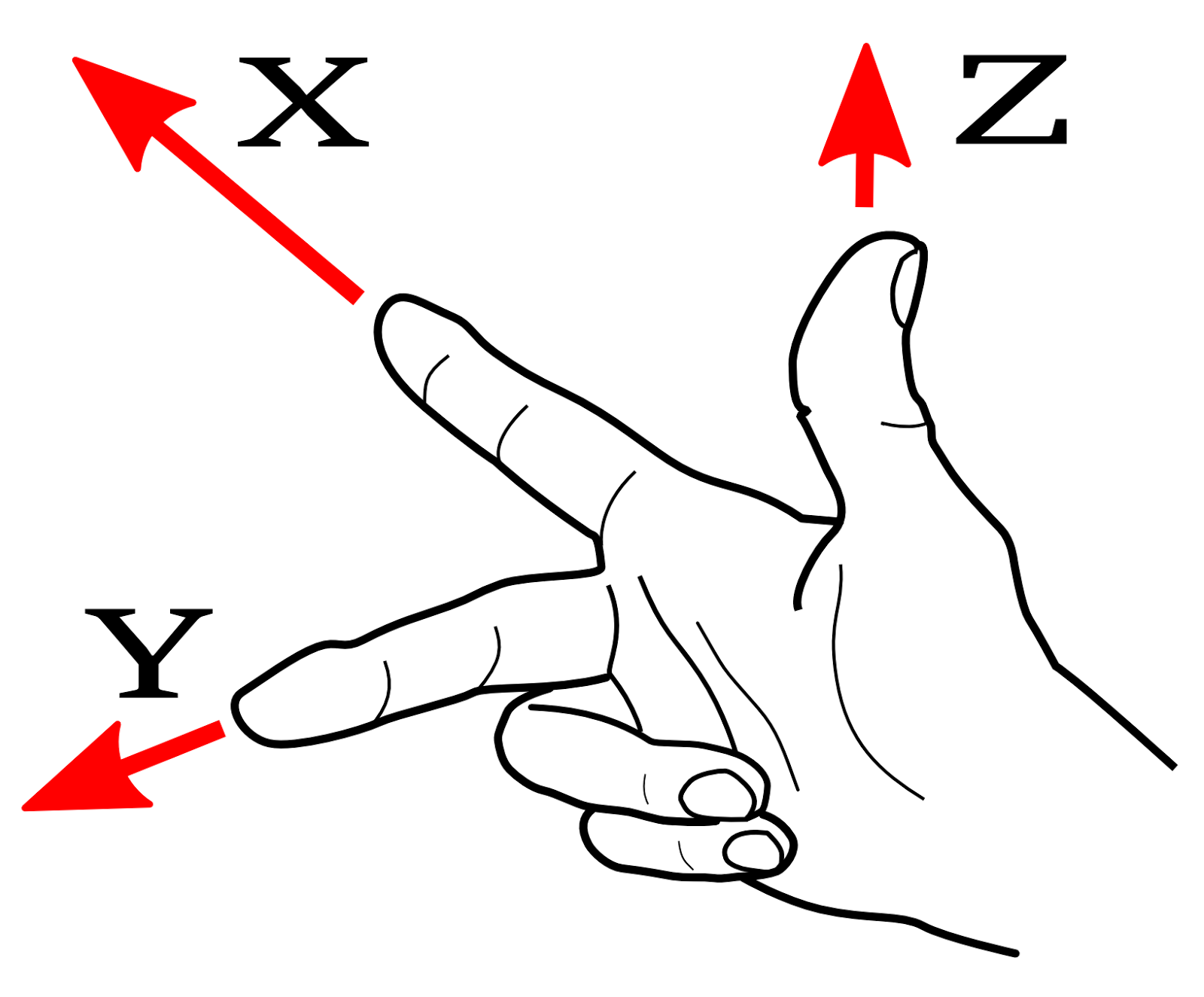
This conventional arrangement of the axes produces a right-handed coordinate system. This means that if you point the thumb of your right hand in the direction of the positive z-axis, then when you curl the fingers of that hand, they will curl in the direction from the positive x-axis towards the positive y-axis.
8.5.1 3D Transformations in OpenGL
The basic transforms in 3D are extensions of the basic transforms that you are already familiar with from 2D: rotation, scaling, and translation. We will look at the 3D equivalents and see how they affect objects when applied as modeling transforms.
glTranslatef(1.0f, 0.0f, 0.0f); // Translate right
glRotatef(45.0f, 0.0f, 1.0f, 0.0f); // Rotate around Y-axis
glScalef(2.0f, 2.0f, 2.0f); // Scale up
8.5.1.1 Examples
glScalef(2,2,2);        // Uniform scaling by a factor of 2.

glScalef(0.5,1,1);      // Shrink by half in the x-direction only.

glScalef(-1,1,1);       // Reflect through the yz-plane.
                        // Reflects the positive x-axis onto negative x.

glTranslatef(5,0,0);    // Move 5 units in the positive x-direction.

glTranslatef(3,5,-7.5); // Move each point (x,y,z) to (x+3, y+5, z-7.5).

glRotatef(90,1,0,0);    // Rotate 90 degrees about the x-axis.
                        // Moves the +y axis onto the +z axis
                        //    and the +z axis onto the -y axis.

glRotatef(-90,-1,0,0);  // Has the same effect as the previous rotation.

glRotatef(90,0,1,0);    // Rotate 90 degrees about the y-axis.
                        // Moves the +z axis onto the +x axis
                        //    and the +x axis onto the -z axis.

glRotatef(90,0,0,1);    // Rotate 90 degrees about the z-axis.
                        // Moves the +x axis onto the +y axis
                        //    and the +y axis onto the -x axis.

glRotatef(30,1.5,2,-3); // Rotate 30 degrees about the line through
                        //    the points (0,0,0) and (1.5,2,-3).
8.5.2 Hierarchy in 3D
Remember that transforms are applied to objects that are drawn after the transformation function is called, and that transformations apply to objects in the opposite order of the order in which they appear in the code.
-
glLoadIdentity()restore the identity matrix -
glPushMatrix()push the current transform to the stack -
glPopMatrix()pop transform from the stack and replace current
Example
void cube(float size) { // Draws a cube with side length = size.
glPushMatrix(); // Save a copy of the current matrix.
glScalef(size,size,size); // Scale unit cube to desired size.
square(1, 0, 0); // red front face
glPushMatrix();
glRotatef(90, 0, 1, 0);
square(0, 1, 0); // green right face
glPopMatrix();
glPushMatrix();
glRotatef(-90, 1, 0, 0);
square(0, 0, 1); // blue top face
glPopMatrix();
glPushMatrix();
glRotatef(180, 0, 1, 0);
square(0, 1, 1); // cyan back face
glPopMatrix();
glPushMatrix();
glRotatef(-90, 0, 1, 0);
square(1, 0, 1); // magenta left face
glPopMatrix();
glPushMatrix();
glRotatef(90, 1, 0, 0);
square(1, 1, 0); // yellow bottom face
glPopMatrix();
glPopMatrix(); // Restore matrix to its state before cube() was called.
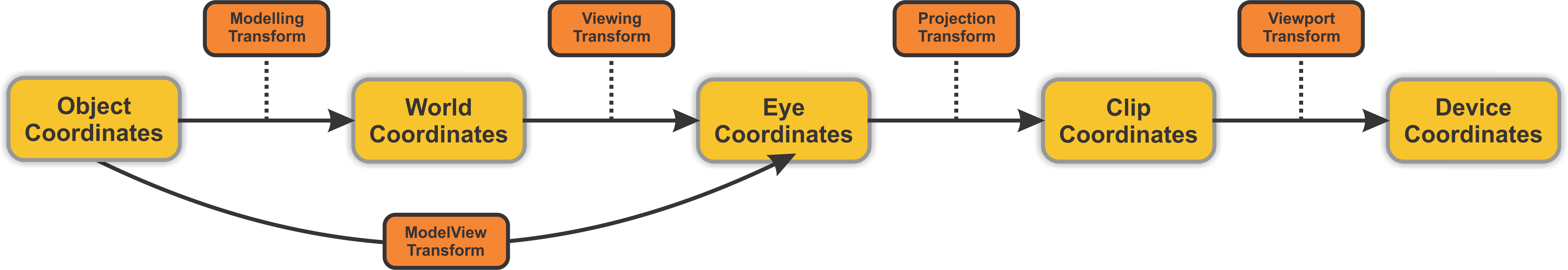
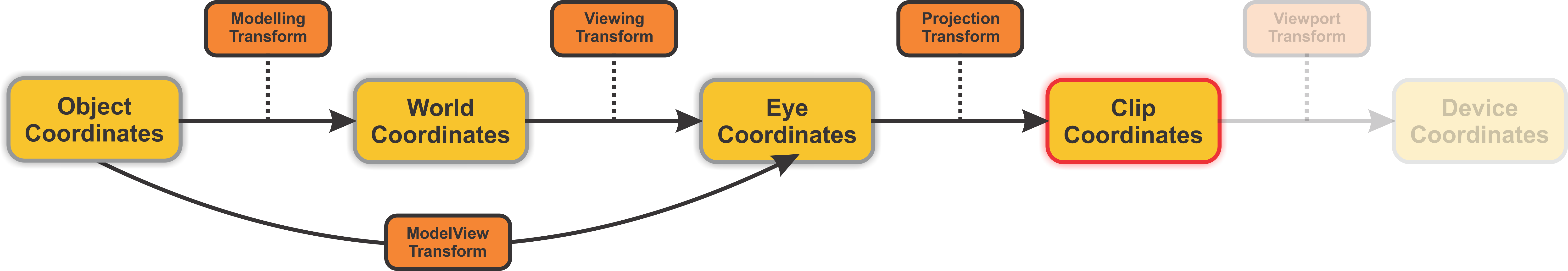
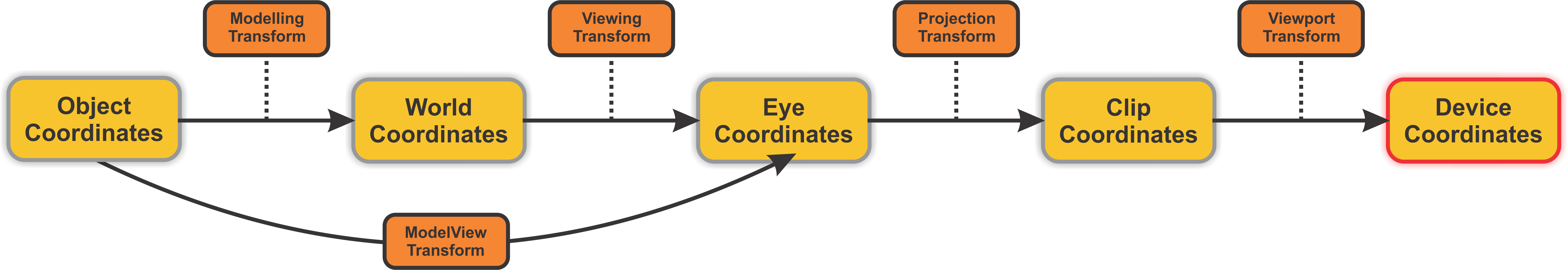
}8.6 Transformation Pipeline
To go from Vertex to Pixel on a screen we require this pipeline of transformations.
8.6.1 Object Coordinates
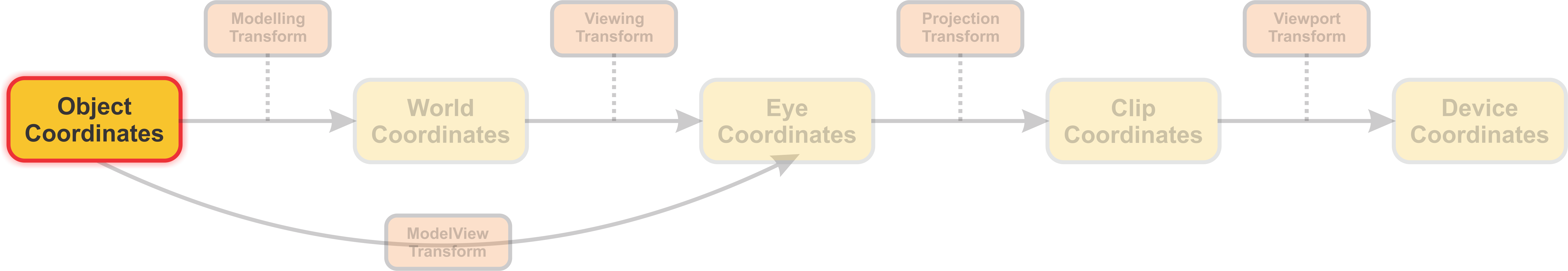
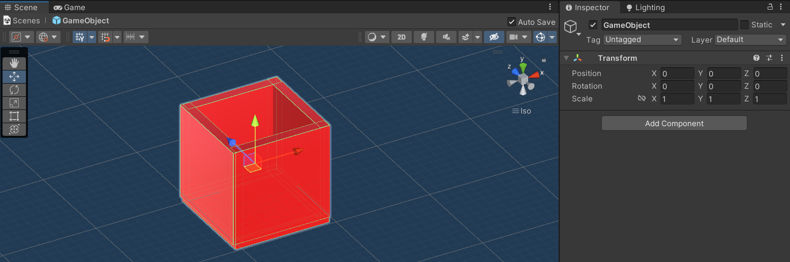
These are the original coordinates of the vertices of a 3D object as defined in its local coordinate space. The object is initially defined relative to its own origin, which is typically at the center of the object.
Here you can see the object is defined locally with its origin at (x=0, y=0, z=0). This is the most natural coordinate system for building objects such that later transformation can be applied intuitively.
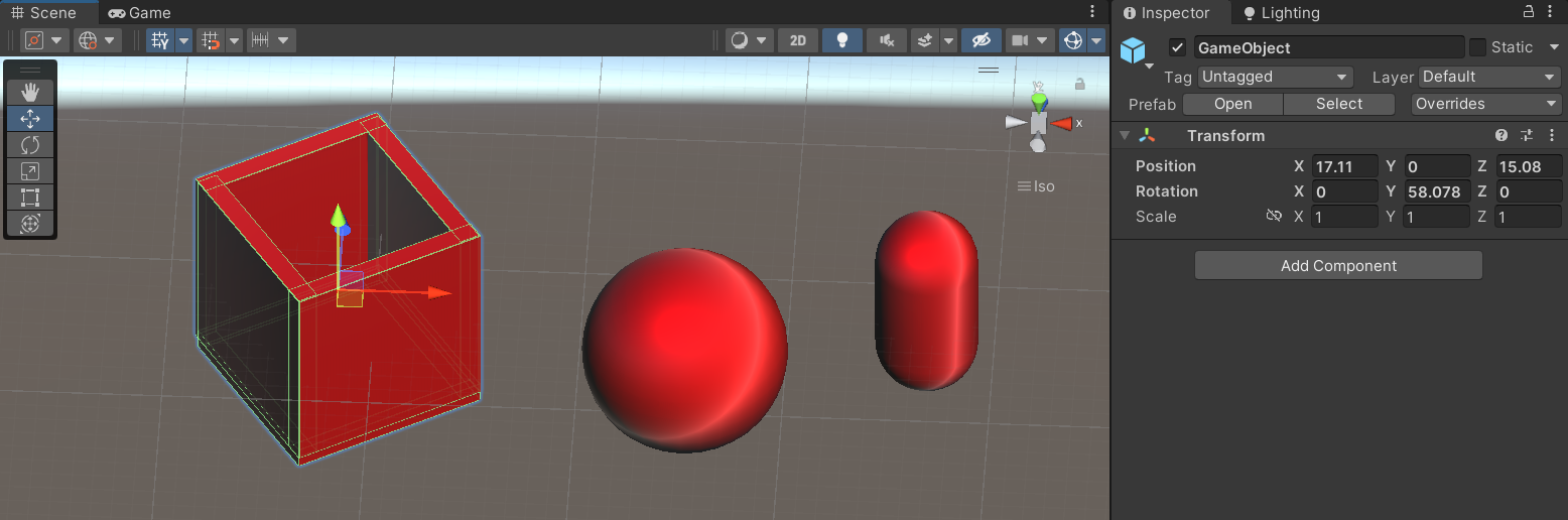
8.6.2 World Coordinates
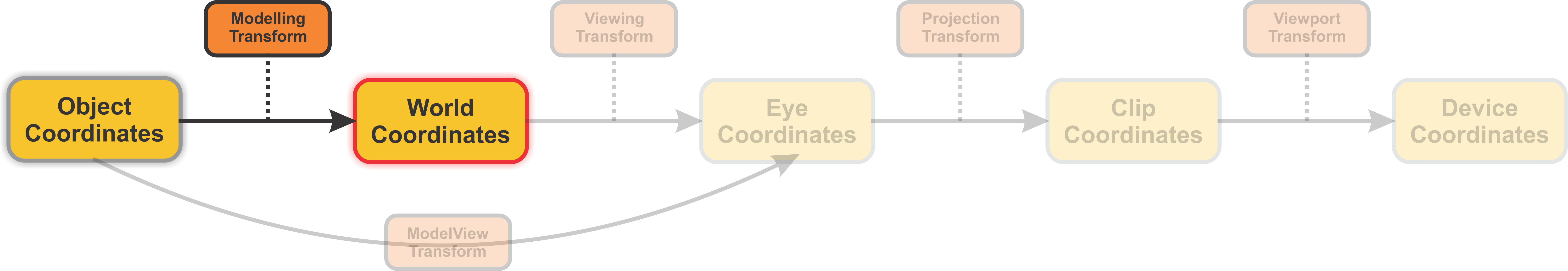
The object coordinates are transformed into world coordinates through the Modeling Transform. This transform positions the object within the larger scene, allowing it to interact with other objects. It essentially translates, rotates, and scales the object from its local coordinate space into the world coordinate space, where all objects in the scene are represented relative to a common origin.
8.6.3 Eye Coordinates
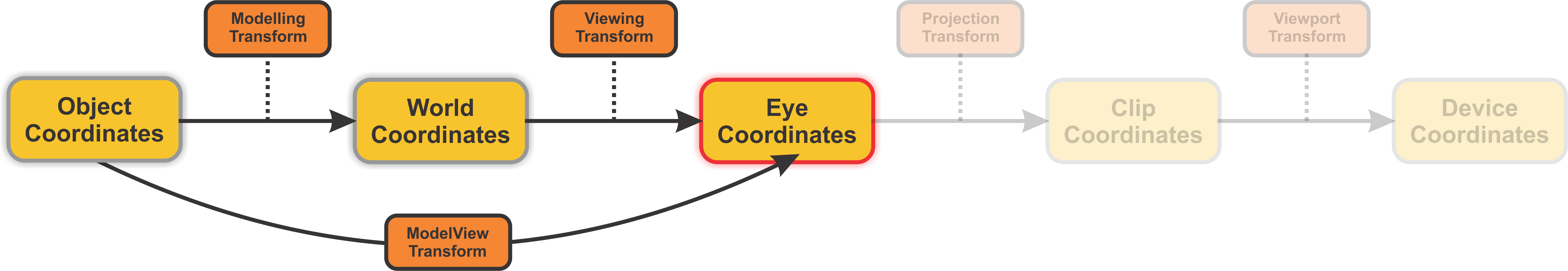
The world coordinates are then transformed into eye coordinates using the Viewing Transform. This step simulates the camera’s point of view. It repositions and reorients the entire scene based on where the camera (or viewer) is placed and which direction it is looking. The resulting eye coordinates represent the positions of objects relative to the camera’s viewpoint.
8.6.3.1 Viewing
The transformation in 3D graphics that maps world coordinates to eye coordinates. The viewing transform establishes the position, orientation, and scale of the viewer in the world, the viewer in this case being the camera.
These transformation can take the form of the following:
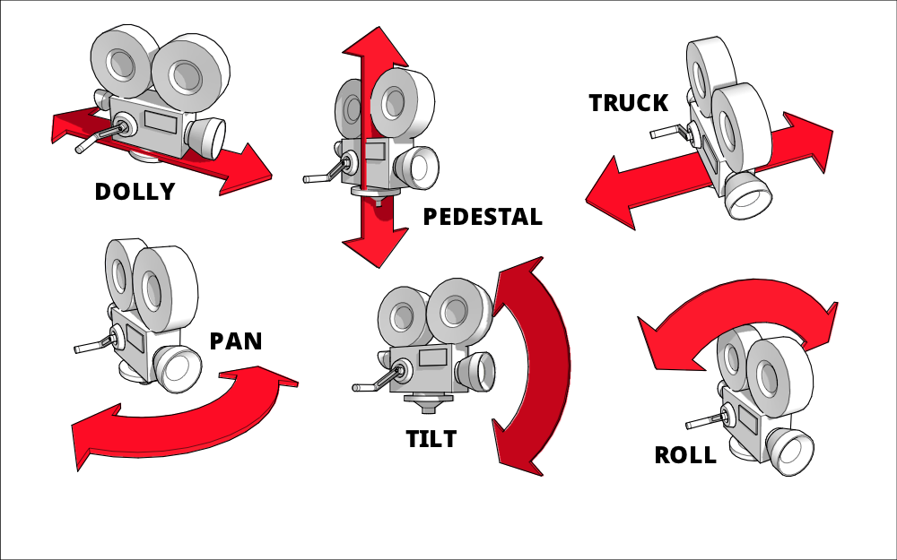
8.6.3.1.1 Zoom
Probably the most well-known camera move, zooming gives the impression of moving closer or further away from the subject.
8.6.3.1.2 Pan
Panning is when the camera is moved horizontally from one side to another on a central axis.

8.6.3.1.3 Tilt
Tilting is similar to panning in that the camera is kept in a stationary position, but unlike panning (which looks from side to side) tilting focuses on upwards & downwards movements.

8.6.3.1.4 Dolly
A dolly shot is when the entire camera is mounted on a track and is moved towards or away from a subject. Unlike a zoom shot, the world around the subject moves with the camera.

8.6.4 Clip Coordinates
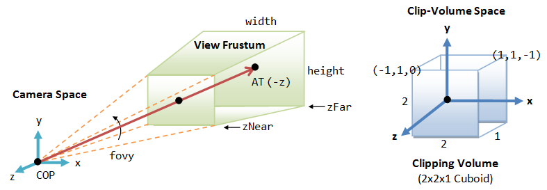
After transforming the coordinates into the eye space, the next step is the Projection Transform. This transform maps the 3D eye coordinates into clip coordinates by applying either a perspective or orthogonal projection. Perspective projection mimics how the human eye perceives the world, with objects farther from the camera appearing smaller, while orthogonal projection maintains the size of objects regardless of their distance from the camera. The result is a set of 4D coordinates (with an additional component for depth) that can be used for further clipping and culling operations, which determine what parts of the scene are visible and should be rendered.
8.6.4.1 Projection
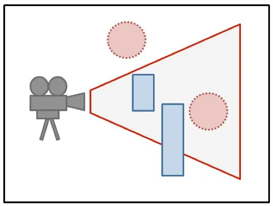
The viewer can’t see the entire 3D world, only the part that fits into the viewport, which is the rectangular region of the screen or other display device where the image will be drawn. We say that the scene is “clipped” by the edges of the viewport. Furthermore, in OpenGL, the viewer can see only a limited range of z-values in the eye coordinate system. Points with larger or smaller z-values are clipped away and are not rendered into the image.
In 3D graphics, a transformation that maps a scene in 3D space onto a 2D image. In OpenGL 1.1, the projection maps the view volume (that is, the region in 3D space that is visible in the image) to clip coordinates, in which the values of x, y, and z range from -1 to 1. The x- and y-coordinates are then mapped to the image, while the z coordinate provides depth information.
The volume of space that is actually rendered into the image is called the view volume. Things inside the view volume make it into the image; things that are not in the view volume are clipped and cannot be seen. For purposes of drawing, OpenGL applies a coordinate transform that maps the view volume onto a cube. The cube is centered at the origin and extends from -1 to 1 in the x-direction, in the y-direction, and in the z-direction. The coordinate system on this cube is referred to as clip coordinates. The transformation from eye coordinates to clip coordinates is called the projection transformation.
8.6.4.1.1 Perspective
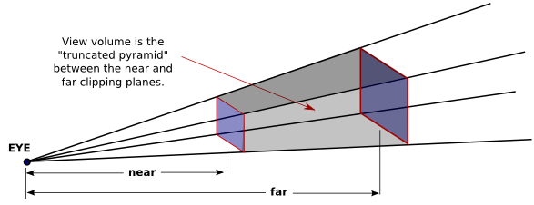
In OpenGL, setting up the projection transformation is equivalent to defining the view volume.
For a perspective transformation, you have to set up a view volume that is a truncated pyramid.
A rather obscure term for this shape is a frustum.
A perspective transformation can be set up with the glFrustum command:
The first four parameters specify the sides of the pyramid: xmin, xmax, ymin, and ymax specify the horizontal and vertical limits of the view volume at the near clipping plane.
The last two parameters specify the near and far distances from the viewer.
The viewer is assumed to be at the origin, (0,0,0), facing in the direction of the negative z-axis.
Since the matrix mode must be set to GL_PROJECTION to work on the projection transformation, glFrustum is often used in a code segment of the form:
8.6.4.1.2 Orthographic
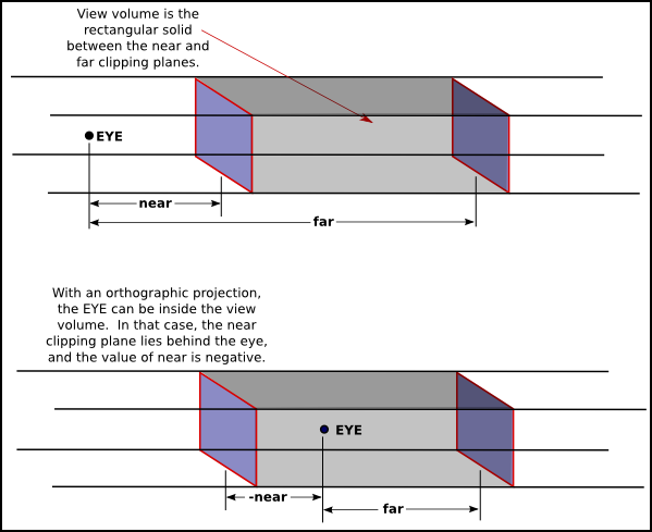
An orthographic projection can be set up in OpenGL using the glOrtho method, which is has the following form:
The first four parameters specify the x- and y-coordinates of the left, right, bottom, and top of the view volume. Note that the last two parameters are near and far.
As with glFrustum, glOrtho should be called when the matrix mode is GL_PROJECTION.
glMatrixMode(GL_PROJECTION);
glLoadIdentity();
glOrtho( -10, 10, -10, 10, -10, 10 );
glMatrixMode(GL_MODELVIEW);
The final step of converting to clip coordinates is to take that view volume and to convert it to a clip volume. The clip volume is a cube centered at (0,0,0) and ranging from (-1,-1,-1) to (1,1,1). This full process can be found here but is supplementary (https://www.songho.ca/opengl/gl_projectionmatrix.html)
8.6.5 Device Coordinates
Finally, the Viewport Transform takes the clip coordinates and maps them to 2D screen space, or Device Coordinates. This step includes normalizing the coordinates to the screen’s resolution and ensuring that they fit within the defined viewport (the area of the screen where the rendering is displayed). The 3D objects are now ready to be rasterized into pixels and displayed on the screen.
8.7 Meshes
OpenGL can only directly render points, lines, and triangles. A polyhedron, the 3D analog of a polygon, can therefore only be represented using these primitives. On the other hand, if only polygons are available, then a curved surface, such as the surface of a sphere, can only be approximated.
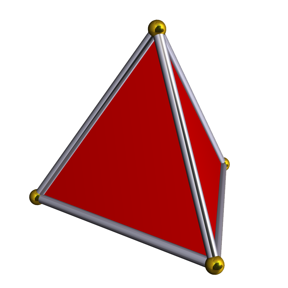
A polyhedron can be represented, or a curved surface can be approximated, as a polygonal mesh, that is, a set of polygons that are connected along their edges. One approach to rendering complex geometry such as meshes is to use Index Faced Sets.
8.7.1 Index Faced Sets
The polygons in a polygonal mesh are also referred to as “faces” (as in the faces of a polyhedron), and one of the primary means for representing a polygonal mesh is as an indexed face set, or IFS.
The data for an IFS includes a list of all the vertices that appear in the mesh, giving the coordinates of each vertex. A vertex can then be identified by an integer that specifies its index, or position, in the list. As an example, consider this “house,” a polyhedron with 10 vertices and 9 faces:
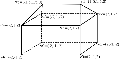
The vertex list for this polyhedron has the form
- Vertex #0. (2, -1, 2)
- Vertex #1. (2, -1, -2)
- Vertex #2. (2, 1, -2)
- Vertex #3. (2, 1, 2)
- Vertex #4. (1.5, 1.5, 0)
- Vertex #5. (-1.5, 1.5, 0)
- Vertex #6. (-2, -1, 2)
- Vertex #7. (-2, 1, 2)
- Vertex #8. (-2, 1, -2)
- Vertex #9. (-2, -1, -2)
To describe one of the polygonal faces of a mesh, we just have to list its vertices, in order going around the polygon. For an IFS, we can specify a vertex by giving its index in the list. For example, we can say that one of the triangular faces of the pyramid is the polygon formed by vertex #3, vertex #2, and vertex #4. So, we can complete our data for the mesh by giving a list of vertex indices for each face. Here is the face data for the house. Remember that the numbers in parentheses are indices into the vertex list:
- Face #0: (0, 1, 2, 3)
- Face #1: (3, 2, 4)
- Face #2: (7, 3, 4, 5)
- Face #3: (2, 8, 5, 4)
- Face #4: (5, 8, 7)
- Face #5: (0, 3, 7, 6)
- Face #6: (0, 6, 9, 1)
- Face #7: (2, 1, 9, 8)
- Face #8: (6, 7, 8, 9)
The vertex and face data for an indexed face set can be represented as single array.
The length of the vertex array would be three times the number of vertices, and the data for vertex number N will begin at index 3*N in the array. For the face list, we have to deal with the fact that not all faces have the same number of vertices. A common solution is to add a -1 to the array after the data for each face. In C, where it is not possible to determine the length of an array, we also need variables to store the number of vertices and the number of faces. Using this representation, the data for the house becomes:
int vertexCount = 10;  // Number of vertices.
double vertexData[] =
          {  2,-1,2, 2,-1,-2, 2,1,-2, 2,1,2, 1.5,1.5,0,
                 -1.5,1.5,0, -2,-1,2, -2,1,2, -2,1,-2, -2,-1,-2  };

int faceCount = 9;  // Number of faces.
int[][] faceData =
          {  0,1,2,3,-1, 3,2,4,-1, 7,3,4,5,-1, 2,8,5,4,-1, 5,8,7,-1,
               0,3,7,6,-1, 0,6,9,1,-1, 2,1,9,8,-1, 6,7,8,9,-1  };
8.7.2 DrawArrays
When using glDrawArrays, all of the data that is needed to draw a primitive, including vertex coordinates, colors, and other vertex attributes, can be packed into arrays. Once that is done, the primitive can be drawn with a single call to glDrawArrays. Recall that a primitive such as a GL_LINE_LOOP or a GL_TRIANGLES can include a large number of vertices, so that the reduction in the number of function calls can be substantial.
To use glDrawArrays, you must store all of the vertex coordinates for a primitive in a single one-dimensional array. You can use an array of int, float, or double, and you can have 2, 3, or 4 coordinates for each vertex. The data in the array are the same numbers that you would pass as parameters to a function such as glVertex3f, in the same order. You need to tell OpenGL where to find the data by calling
- The
sizeparameter is the number of coordinates per vertex. - The
typeis a constant that tells the data type of each of the numbers in the array. The possible values are GL_FLOAT, GL_INT, and GL_DOUBLE. - The
strideis usually 0, meaning that the data values are stored in consecutive locations in the array. - The final parameter is the
arraythat contains the data.
In addition to setting the location of the vertex coordinates, you have to enable use of the array by calling
Finally, in order to actually draw the primitive, you would call the function
- The
primitiveTypetells which primitive type is being drawn, such as GL_QUADS or GL_TRIANGLE_STRIP. - The parameter
firstVertexis the number of the first vertex that is to be used for drawing the primitive. - The
vertexCountparameter is the number of vertices to be used.
Often there is other data associated with each vertex in addition to the vertex coordinates. For example, you might want to specify a different color for each vertex. The colors for the vertices can be put into another array. You have to specify the location of the data by calling
which works just like gVertexPointer. And you need to enable the color array by calling
With this setup, when you call glDrawArrays, OpenGL will pull a color from the color array for each vertex at the same time that it pulls the vertex coordinates from the vertex array
8.7.3 DrawElements
The function glDrawElements is similar to glDrawArrays, but it is designed for use with data in a format similar to an indexed face set. With glDrawArrays, OpenGL pulls data from the enabled arrays in order, vertex 0, then vertex 1, then vertex 2, and so on. With glDrawElements, you provide a list of vertex numbers. OpenGL will go through the list of vertex numbers, pulling data for the specified vertices from the arrays. The advantage of this comes, as with indexed face sets, from the fact that the same vertex can be reused several times.
To use glDrawElements to draw a primitive, you need an array to store the vertex numbers. The numbers in the array can be 8, 16, or 32 bit integers. (They are supposed to be unsigned integers, but arrays of regular positive integers will also work.) You also need arrays to store the vertex coordinates and other vertex data, and you must enable those arrays in the same way as for glDrawArrays, using functions such as glVertexArray and glEnableClientState. To actually draw the primitive, call the function
-
primitiveTypeis one of the ten primitive types such as GL_LINES. -
vertexCountis the number of vertices to be drawn. -
dataTypespecifies the type of data in the array, and array is the array that holds the list of vertex numbers. The dataType must be given as one of the constants GL_UNSIGNED_BYTE, GL_UNSIGNED_SHORT, or GL_UNSIGNED_INT to specify 8, 16, or 32 bit integers respectively.
Example
float vertexCoords[24] = {  // Coordinates for the vertices of a cube.
           1,1,1,   1,1,-1,   1,-1,-1,   1,-1,1,
          -1,1,1,  -1,1,-1,  -1,-1,-1,  -1,-1,1  };

float vertexColors[24] = {  // An RGB color value for each vertex
           1,1,1,   1,0,0,   1,1,0,   0,1,0,
           0,0,1,   1,0,1,   0,0,0,   0,1,1  };

int elementArray[24] = {  // Vertex numbers for the six faces.
          0,1,2,3, 0,3,7,4, 0,4,5,1,
          6,2,1,5, 6,5,4,7, 6,7,3,2  };

glVertexPointer( 3, GL_FLOAT, 0, vertexCoords );
glColorPointer( 3, GL_FLOAT, 0, vertexColors );

glEnableClientState( GL_VERTEX_ARRAY );
glEnableClientState( GL_COLOR_ARRAY );

glDrawElements( GL_QUADS, 24, GL_UNSIGNED_INT, elementArray );