9 Lighting
9.1 Introduction
One important aspect of physical realism is lighting: the play of light and shadow, the way that light reflects from different materials, the way it can bend or be diffracted as it passes through translucent objects. The techniques that are used to produce the most realistic graphics can take all these factors and more into account.
However, another goal of computer graphics is speed. OpenGL, in particular, was designed for real-time graphics, where the time that is available for rendering an image is a fraction of a second. For an animated movie, it’s OK if it takes hours to render each frame. But a video game is expected to render sixty frames every second. Even with the incredible speed of modern computer graphics hardware, compromises are necessary to get that speed. And thirty years ago, when OpenGL was still new, the compromises were a lot bigger
9.1.1 Offline Rendering
Offline rendering refers to the process of generating images, animations, or other visual content without the need for immediate display. This method is typically used in scenarios where high-quality output is required, but time is not a constraint. Offline rendering allows for complex computations, advanced lighting models, and intricate effects that might not be feasible in real-time.
9.1.2 Real-time Rendering
Real-time rendering, on the other hand, is the process of generating images on the fly, typically within milliseconds, so that they can be displayed immediately. This method is crucial for interactive applications, such as video games, simulations, and virtual reality, where the visuals need to respond instantaneously to user inputs.
9.2 Lights
Light is a form of electromagnetic radiation that is visible to the human eye. The visible spectrum is the portion of the electromagnetic spectrum that can be detected by the human eye.
In computer graphics, light refers to the simulated representation of illumination in a 3D environment. Light is used to enhance the realism and visual appeal of scenes by mimicking how real-world light interacts with objects.
9.2.1 Types
Various types of lights allow artists and designers to create realistic and dynamic lighting setups tailored to the needs of their specific scene or project.
9.2.1.1 Point
- A point light emits light uniformly in all directions from a single point in space, similar to a light bulb. It doesn’t have a specific shape, and the intensity of the light diminishes with distance.
- Point lights are used to simulate small, localized light sources such as a lamp, candle, or firefly.
9.2.1.2 Directional
- A directional light simulates light coming from a specific direction, like sunlight. It is considered to have an infinite distance from the scene, so all rays are parallel, and the light does not diminish with distance.
- This type of light is typically used to simulate sunlight or moonlight, where the light source is far away, and the light rays are almost parallel.
9.2.1.3 Spot
- A spotlight emits light in a cone shape from a single point, with the intensity falling off as it moves away from the central axis of the cone. The spotlight can be adjusted to focus on a specific area, and the beam can be softened or sharpened.
- Spotlights are commonly used to simulate focused light sources like stage lights, flashlights, or car headlights.
9.2.1.4 Area
- An area light emits light from a defined area, such as a rectangle or disc, rather than a single point. This type of light produces soft shadows and realistic lighting because it mimics the behavior of larger light sources like windows or fluorescent lights.
- Area lights are ideal for simulating light sources with a defined shape, such as windows, TV screens, or softbox lights in photography.
9.2.1.5 Properties
When defining a light in a 3D rendering program, several properties or attributes are typically used to control how the light behaves and how it affects the scene
- Position
- Direction
- Intensity
- Falloff
- Range
- Colour
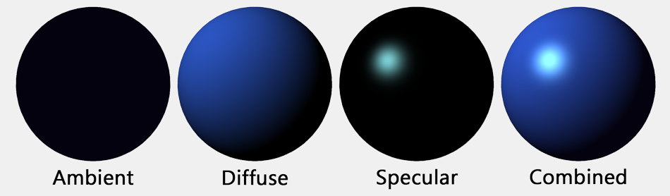
In most programs including OpenGL, each light source has three colours:
- ambient colour
- diffuse colour
- specular colour
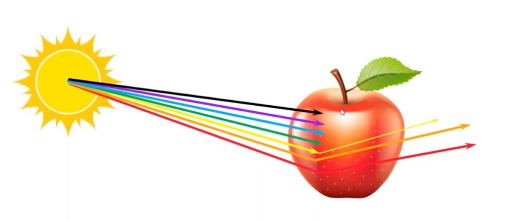
Just as the colour of a material is more properly referred to as reflectivity, colour of a light is more properly referred to as intensity or energy. More exactly, colour refers to how the light’s energy is distributed among different wavelengths. Real light can contain an infinite number of different wavelengths; when the wavelengths are separated, you get a spectrum or rainbow containing a continuum of colours.
Light as it is usually modelled on a computer contains only the three basic colours, red, green, and blue. So, just like material colour, light colour is specified by giving three numbers representing the red, green, and blue intensities of the light.
The diffuse intensity of a light is the aspect of the light that interacts with diffuse material colour, and the specular intensity of a light is what interacts with specular material colour. It is common for the diffuse and specular light intensities to be the same.
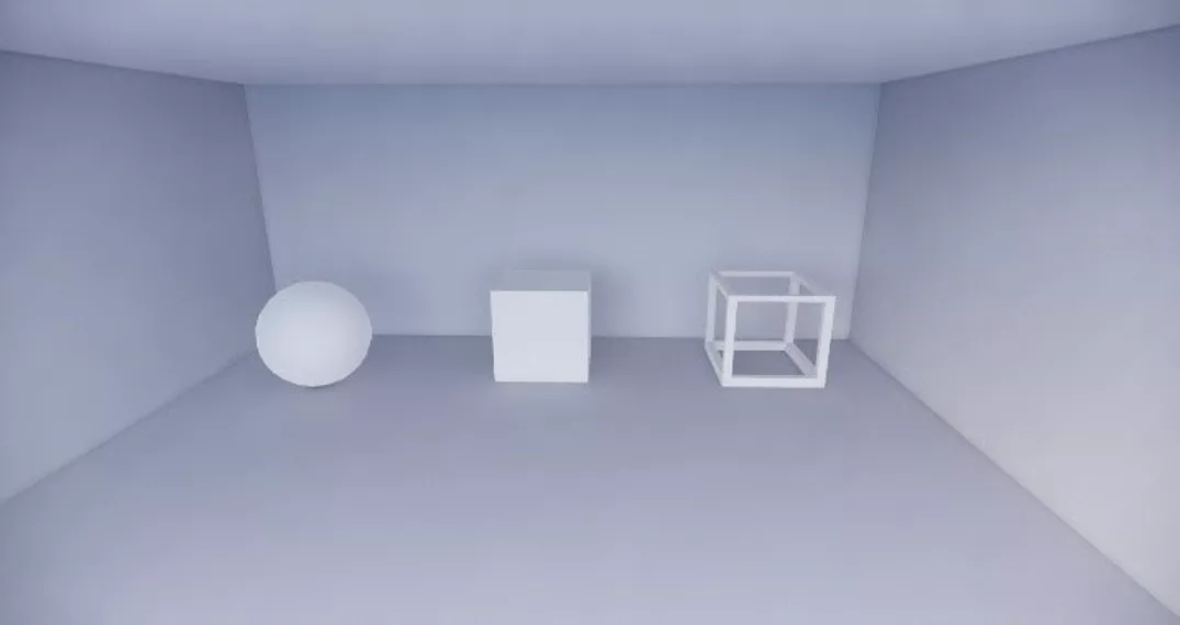
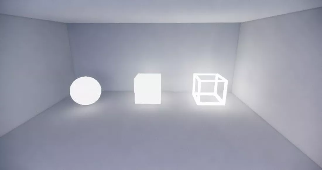
9.3 Reflection
Reflection in computer graphics refers to the complex simulation of how light interacts with surfaces to create mirrored or reflective effects. When light strikes a surface, some of it will be reflected. Exactly how it reflects depends on the nature of the surface (material properties of the surface).

In OpenGL 1.1, this complexity is approximated by two general types of reflection, specular reflection and diffuse reflection.
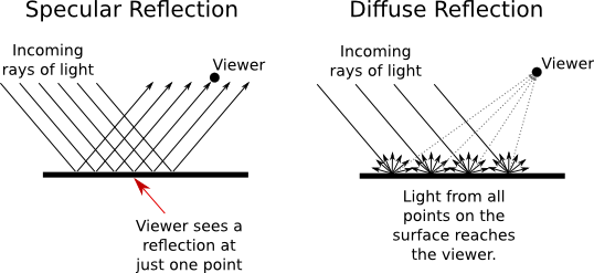
9.3.1 Diffuse
Reflection of incident light in all directions from a surface, so that diffuse illumination of a surface is visible to all viewers, independent of the viewer’s position.
9.3.2 Specular
In perfect specular (“mirror-like”) reflection, an incoming ray of light is reflected from the surface intact. The reflected ray makes the same angle with the surface as the incoming ray. A viewer can see the reflected ray only if the viewer is in exactly the right position, somewhere along the path of the reflected ray. Even if the entire surface is illuminated by the light source, the viewer will only see the reflection of the light source at those points on the surface where the geometry is right. Such reflections are referred to as specular highlights.
In practice, we think of a ray of light as being reflected not as a single perfect ray, but as a cone of light, which can be more or less narrow.
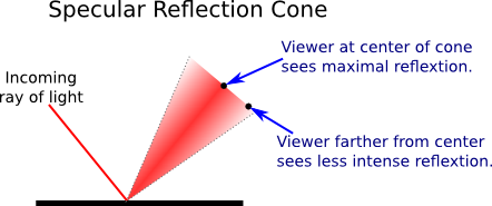
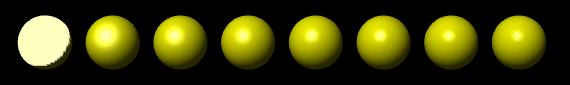
9.3.2.1 Shininess
Specular reflection from a very shiny surface produces very narrow cones of reflected light; specular highlights on such a material are small and sharp. A duller surface will produce wider cones of reflected light and bigger, fuzzier specular highlights.
In OpenGL, the material property that determines the size and sharpness of specular highlights is called shininess. Shininess in OpenGL is a number in the range 0 to 128. As the number increases, specular highlights get smaller.
9.4 Material
The properties of an object determine how that object interacts with light in the environment. Material properties in OpenGL include, for example, diffuse colour, specular colour, and shininess.
9.4.1 Colour
When light strikes a surface, some of the light can be absorbed, some can be reflected diffusely, and some can be reflected specularly. The amount of reflection can be different for different wavelengths. The degree to which a material reflects light of various wavelengths is what constitutes the colour of the material.
We now see that a material can have two different colors—a diffuse colour that tells how the material reflects light diffusely, and a specular colour that tells how it reflects light specularly.
9.4.1.1 Diffuse
A material property that represents the proportion of incident light that is reflected diffusely from a surface.
9.4.1.2 Specular
A material property that represents the proportion of incident light that is reflected specularly by a surface.
9.4.1.3 Ambient
A material property that represents the proportion of ambient light in the environment that is reflected by a surface.
Ambient light refers to a general level of illumination that does not come directly from a light source. It consists of light that has been reflected and re-reflected so many times that it is no longer coming from any particular direction. Ambient light is why shadows are not absolutely black. In fact, ambient light is only a crude approximation for the reality of multiply reflected light, but it is better than ignoring multiple reflections entirely. The ambient colour of a material determines how it will reflect various wavelengths of ambient light. Ambient colour is generally set to be the same as the diffuse colour.
9.4.2 Transparency
Each of the four material colour properties is specified in terms of three numbers giving the RGB (red, green, and blue) components of the colour. Material colours can also have alpha components, but the only alpha component that is ever used in OpenGL is the one for the diffuse material colour. It is most often used to specify the degree of transparency of a colour.
9.5 Shading
In computer graphics, shading refers to the process of determining the Colour and brightness of surfaces in a 3D scene based on the interaction of light with those surfaces. Shading is essential for creating the illusion of depth, texture, and realism in a rendered image by simulating how light affects different materials.
Key Concepts in Shading:
-
Surface Normals
- Description: Surface normals are vectors perpendicular to a surface that are used in shading calculations. They indicate the direction that the surface is facing, which is crucial for determining how light interacts with that surface.
- Role in Shading: The angle between the surface normal and the light source affects the brightness and Colour of the surface.
-
Lighting Models
- Description: Lighting models (or shading models) are mathematical models that describe how light interacts with surfaces. These models determine the final Colour of a pixel based on light sources, surface properties, and viewing angles.
9.5.1 Normals
The visual effect of a light shining on a surface depends on the properties of the surface and of the light. But it also depends to a great extent on the angle at which the light strikes the surface.
The angle is essential to specular reflection and also affects diffuse reflection. That’s why a curved, lit surface looks different at different points, even if its surface is a uniform colour.
To calculate this angle, OpenGL needs to know the direction in which the surface is facing. That direction is specified by a vector that is perpendicular to the surface. A vector that is perpendicular to a surface at a given point is called a normal vector to that surface. When used in lighting calculations, a normal vector must have length equal to one. A normal vector of length one is called a unit normal.
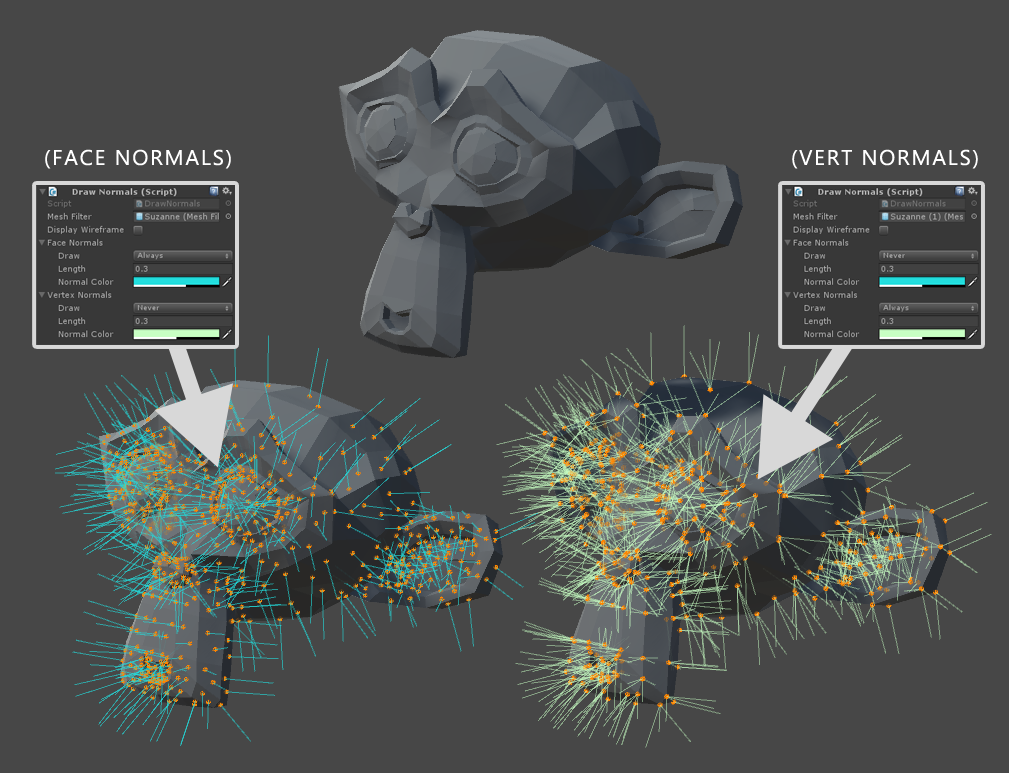
There are two types of normal vectors:
Surface Normals: A surface normal is a vector that is perpendicular to the surface of a polygon (typically a triangle or quadrilateral) at a given point. For a flat polygonal surface, this normal is usually the same across the entire surface.
Vertex Normals: A vertex normal is a vector that is associated with a vertex of a 3D model. Unlike surface normals, which are constant over the surface of a polygon, vertex normals can vary at each vertex. Vertex normals are typically calculated as the average of the normals of the polygons that share the vertex.
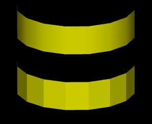
9.5.2 Flat Shading
Definition: Flat shading applies a single color and lighting calculation to each polygon (or face) of the 3D model. This means that each polygon is rendered with a uniform color, without any gradients.
Appearance: The result is a faceted look where the edges of polygons are clearly visible. The model looks more angular, and you can easily distinguish between different polygons.
Performance: Flat shading is computationally cheaper because it requires fewer calculations. Only one normal per face is used to compute the lighting.
Use Cases: Flat shading is often used for stylistic purposes, in retro games, or in cases where the geometric shape of the object should be emphasized.
9.5.3 Smooth Shading
Definition: Smooth shading, on the other hand, interpolates the lighting calculations across the surface of a polygon. Each vertex of the polygon has its own normal, and these normals are used to compute lighting across the surface, creating a gradient effect.
Appearance: The result is a smooth, rounded appearance where transitions between polygons are less noticeable. This technique makes the surface appear more curved and less faceted.
Performance: Smooth shading is more computationally intensive than flat shading because lighting must be calculated at each vertex and then interpolated across the polygon’s surface.
Use Cases: Smooth shading is commonly used in modern 3D graphics for realistic rendering, where smooth transitions between surfaces are desired.
9.5.4 Cell Shading
Cell shading, also known as cel shading, is a style of non-photorealistic rendering designed to make computer graphics appear to be hand-drawn. This technique is often used in animation and video games to mimic the style of comic books or cartoons. It emphasizes distinct colour blocks and boundaries rather than gradual colour transitions, creating a flat, two-dimensional appearance.


9.6 OpenGL Lighting Equation
The goal of the calculation is to produce a colour, (r,g,b,a), for a point on a surface. In OpenGL 1.1, lighting calculations are actually done only at the vertices of a primitive. After the colour of each vertex has been computed, colours for interior points of the primitive are obtained by interpolating the vertex colours.
9.6.1 The Equation
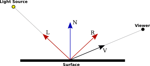
- \(N\) is the normal vector at the point whose colour we want to compute.
- \(L\) is a vector that points back along the direction from which the light arrives at the surface.
- \(V\) is a vector that points in the direction of the viewer.
- \(R\) is the direction of the reflected ray, that is, the direction in which a light ray from the source would be reflected specularly when it strikes the surface at the point in question.
Now, let’s say that the light has ambient, diffuse, and specular colour components \((l_{ar},l_{ag},l_{ab})\), \((l_{dr},l_{dg},l_{db})\), and \((l_{sr},l_{sg},l_{sb})\). Also, let \(m_h\) be the value of the shininess property of the material. Then, assuming that the light is enabled, the contribution of this light source to the red component of the vertex colour can be computed as
\(I_{r} = l_{ar}*m_{ar} + f*( l_{dr}*m_{dr}*(L·N) + l_{sr}*m_{sr}*max(0,V·R)^{m_h})\)
or
\(I = I_{ambient} + I_{diffuse} + I_{specular}\)
This equation can be dissected into several parts:
- \(I_r\): This is the resulting intensity of the reflected light perceived by the viewer.
- \(f\): This is a factor that might include the attenuation of light due to distance or other effects like shadowing.
9.6.1.1 Ambient Lighting Component
\(I_{ambient} = l_{material\_ambient} \times l_{light\_ambient}\)
- Ambient lighting is the simplest component and represents the base level of illumination in a scene. It simulates light that is scattered in all directions, uniformly lighting up all surfaces regardless of their orientation.
- Material Ambient Reflectance (\(l_{material\_ambient}\)): This represents how much of the ambient light the surface material reflects. It’s a property of the material and is usually specified as a Colour.
- Light Ambient Colour (\(l_{light\_ambient}\)): This represents the Colour and intensity of the ambient light in the scene.
The product of these two factors gives the ambient contribution to the final Colour of the surface. This ensures that no surface is completely dark, even if it’s not directly lit by any light source.
9.6.1.2 Diffuse Lighting Component
\(I_{diffuse} = l_{material\_diffuse} \times l_{light\_diffuse} \times \max(0, \vec{N} \cdot \vec{L})\)
- Diffuse lighting models how light interacts with rough surfaces, where light is scattered in many directions. This component depends on the angle between the light direction and the surface normal.
- Material Diffuse Reflectance (\(l_{material\_diffuse}\)): This is the Colour of the material under diffuse lighting, representing how much light the material reflects diffusely.
- Light Diffuse Colour (\(l_{light\_diffuse}\)): This represents the Colour and intensity of the diffuse light.
Dot Product (\(\vec{N} \cdot \vec{L}\)):
- \(\vec{N}\) is the surface normal, a vector perpendicular to the surface at the point of interest.
- \(\vec{L}\) is the light direction vector, pointing from the surface point towards the light source.
- The dot product \(\vec{N} \cdot \vec{L}\) calculates the cosine of the angle between these two vectors. This determines how much light is received by the surface based on its orientation relative to the light source.
- The \(\max(0, \vec{N} \cdot \vec{L})\) ensures that the diffuse component is zero when the light is not hitting the surface (i.e., when the angle is greater than 90 degrees).
9.6.1.3 Specular Lighting Component
\(I_{specular} = l_{material\_specular} \times I_{light\_specular} \times (\max(0, \vec{R} \cdot \vec{V}))^{m_h}\)
- Specular lighting simulates the reflection of light from shiny surfaces, creating highlights that depend on the viewer’s position.
- Material Specular Reflectance (\(I_{material\_specular}\)): This represents the Colour of the specular highlight and indicates how shiny or reflective the material is.
- Light Specular Colour (\(I_{light\_specular}\)): This represents the Colour and intensity of the specular light.
- Shininess (\(m_h\))
Reflection Vector (\(\vec{R}\)):
- The reflection vector \(\vec{R}\) is computed based on the surface normal and the light direction. It represents the direction that a perfectly reflected ray of light would take.
- The reflection vector is calculated as: \(\vec{R} = 2(\vec{N} \cdot \vec{L})\vec{N} - \vec{L}\)
Viewer Direction (\(\vec{V}\)):
- \(\vec{V}\) is the direction from the surface point towards the viewer or camera.
Specular Highlight Calculation:
- The dot product \(\vec{R} \cdot \vec{V}\) calculates the cosine of the angle between the reflection vector and the view direction. This determines the intensity of the specular highlight.
- The exponent \(m_h\) controls the size and sharpness of the specular highlight. A higher shininess value results in a smaller, sharper highlight, simulating a very shiny surface.
9.6.2 Worked Example: Using the OpenGL 1.1 Lighting Equation
In this example, we will calculate the Colour of a vertex in a 3D scene using the OpenGL 1.1 lighting equation. The equation considers ambient, diffuse, and specular lighting components to determine the final Colour at the vertex.
9.6.2.1 Given Data
9.6.2.1.1 Material Properties:
-
Ambient Material Colour (
l_material_ambient): (0.2, 0.2, 0.2) -
Diffuse Material Colour (
l_material_diffuse): (0.8, 0.0, 0.0) (red Colour) -
Specular Material Colour (
l_material_specular): (1.0, 1.0, 1.0) -
Shininess (
shininess): 32
9.6.2.2 Step 1: Calculate the Ambient Component
\(I_{ambient} = l_{material\_ambient} \times l_{light\_ambient}\) \(I_{ambient} = (0.2, 0.2, 0.2) \times (0.1, 0.1, 0.1) = (0.02, 0.02, 0.02)\)
9.6.2.3 Step 2: Calculate the Diffuse Component
\(I_{diffuse} = l_{material\_diffuse} \times l_{light\_diffuse} \times \max(0, \vec{N} \cdot \vec{L})\)
9.6.2.4 Step 3: Calculate the Specular Component
\(I_{specular} = l_{material\_specular} \times l_{light\_specular} \times (\max(0, \vec{R} \cdot \vec{V}))^{shininess}\)
9.6.2.5 Step 4: Combine the Components
\(I = I_{ambient} + I_{diffuse} + I_{specular}\)
\(I = (0.02, 0.02, 0.02) + (0.8, 0.0, 0.0) + (1.0, 1.0, 1.0)\)
\(I = (1.82, 1.02, 1.02)\)
Since Colour values are clamped to the range [0, 1] in OpenGL:
\(I = \min((1.82, 1.02, 1.02), (1.0, 1.0, 1.0)) = (1.0, 1.0, 1.0)\)
9.7 OpenGL Code Example
9.7.1 Defining Lights
In OpenGL 1.1, the use of light and material must be enabled by calling:
To light a scene, in addition to enabling GL_LIGHTING, you must configure at least one source of light. For very basic lighting, it often suffices to call:
This command turns on a directional light that shines from the direction of the viewer into the scene. Since it shines from the direction of the viewer, it will illuminate everything that the user can see. The light is white, with no specular component.
OpenGL 1.1 supports at least eight light sources, which are identified by the constants GL_LIGHT0, GL_LIGHT1, …, GL_LIGHT7.
However, just enabling a light does not give any illumination, except in the case of GL_LIGHT0, since all light intensities are zero by default, with the single exception of the diffuse color of light number 0. To get any light from the other light sources, you need to change some of their properties. Light properties can be set using the functions
For example, to set up light GL_LIGHT1 as a bluish light, with blue specular highlights, that adds a bit of blue to the ambient light when it is turned on, you might use:
float blue1[4] = { 0.4, 0.4, 0.6, 1 };
float blue2[4] = { 0, 0, 0.8, 1 };
float blue3[4] = { 0, 0, 0.15, 1 };
glLightfv( GL_LIGHT1, GL_DIFFUSE, blue1 );
glLightfv( GL_LIGHT1, GL_SPECULAR, blue2 );
glLightfv( GL_LIGHT1, GL_AMBIENT, blue3 );
To set the position and type of light we use the GL_POSITION property. The property value for GL_POSITION is an array of four numbers (x,y,z,w).
- if
wis zero, then the light is directional and the point(x,y,z)specifies the direction of the light. - if
wis non-zero, then the light is a point light, and it is located at the point(x/w, y/w, z/w). Usually,wis1. The value (x,y,z,1) gives a point light at (x,y,z).
For example,
9.7.2 Defining Materials
With all that in mind, we will look at functions for setting the current values of material properties. For setting the ambient, diffuse, specular, and emission material colors, the function is
- side :
GL_FRONT_AND_BACK,GL_FRONT, orGL_BACK. It tells whether you are setting a material property value for the front face, the back face, or both. - property : The second parameter tells which material property is being set. It can be
GL_AMBIENT,GL_DIFFUSE,GL_SPECULAR,GL_EMISSION, orGL_AMBIENT_AND_DIFFUSE. - valueArray : An array containing four float numbers. The numbers give the RGBA color components as values in the range from 0.0 to 1.0.
Suppose for example that we want to set the ambient and diffuse colors to a bluish green. In C, that might be done with:
9.7.3 Defining Normals
Functions in the family glNormal* include glNormal3f, glNormal3d, glNormal3fv, and glNormal3dv are used to define vertex normals. As usual, a “v” means that the values are in an array, “f” means that the values are floats, and “d” means that the values are doubles. (All normal vectors have three components). Some examples:
glNormal3f( 0, 0, 1 );  // (This is the default value.)
glNormal3d( 0.707, 0.707, 0.0 );
float normalArray[3] = { 0.577, 0.577, 0.577 };
glNormal3fv( normalArray );
For a polygon that is supposed to look flat, the same normal vector is used for all of the vertices of the polygon. For example, to draw one side of a cube, say the “top” side, facing in the direction of the positive y-axis: