10 The Programmable Pipeline
10.1 Introduction
In the early days of computer graphics, the rendering pipeline was a fixed-function system, where the stages of rendering were hard-coded by the hardware. Developers had limited control over the fine details of how their graphics were processed. This approach was sufficient for basic rendering tasks, but as the demand for more sophisticated visuals grew, the limitations of the fixed-function pipeline became apparent.
The introduction of the programmable graphics pipeline revolutionized the field by allowing developers to write custom code—called shaders—to control various stages of the pipeline. This shift empowered artists and programmers to push the boundaries of visual fidelity and create more dynamic, realistic, and interactive environments.
10.1.1 fixed-function pipeline
A graphics processing pipeline with a fixed set of processing stages that cannot be modified by a programmer. Data for an image passes through a sequence of processing stages, with the image as the end product. The sequence is called a “pipeline.” With a fixed-function pipeline, the programmer can enable and disable stages and set options that control the processing but cannot add to the functionality.
10.1.2 programmable pipeline
A graphics processing pipeline in which some of the processing stages can or must be implemented by programs. Data for an image passes through a sequence of processing stages, with the image as the end product. The sequence is called a “pipeline.” Programmable pipelines are used in modern GPUs to provide more flexibility and control to the programmer. The programs for a programmable pipeline are known as shaders and are written in a shader programming language such as GLSL.
10.2 Shaders
Shaders are small programs that run on the GPU, designed to control the rendering pipeline. They allow for high levels of customization in the visual output of computer graphics applications, including games, simulations, and visual effects.
Drawing with WebGL requires a shader program, which consists of a vertex shader and a fragment shader. Shaders are written in the language GLSL ES 1.0 (the OpenGL Shader Language for Embedded Systems, version 1.0).
10.2.1 Vertex Shader
The Vertex Shader is the first programmable stage in the graphics pipeline. It processes each vertex of the geometry individually. The main responsibilities of a vertex shader include transforming vertex coordinates from model space to screen space and passing per-vertex data like color, texture coordinates, and normals to the next stages of the pipeline.
10.2.2 Fragment Shader
The Fragment Shader operates on each fragment that will potentially form part of the final pixel color in the rendered image. It is responsible for setting the color of pixels based on various inputs, including data passed from the vertex shader, and can perform complex computations to create effects like texturing, shading, and lighting.
10.3 Data Structures
10.3.1 glMatrix
glMatrix is a popular library for handling matrix and vector operations in WebGL. It is optimized for high performance in graphics computations.
const projection = mat4.create();    // projection matrix
const modelview = mat4.create();     // modelview matrix
const modelviewProj = mat4.create(); // combined transformation matrix
const normalMatrix = mat3.create(); // matrix, derived from modelview matrix, for transforming normal vectors

mat4.multiply( modelviewProj, projection, modelview ); //Multiply the modelview and projection transforms to get the combined transform
10.3.2 VBOs
Vertex Buffer Object. A block of memory that can hold the coordinates or other attributes for a set of vertices. A VBO can be stored on a GPU. VBOs make it possible to send such data to the GPU once and then reuse it several times. In OpenGL, VBOs are used with the functions glDrawArrays and glDrawElements.
function drawPrimitive( primitiveType, color, vertices ) {
     gl.enableVertexAttribArray(a_coords_loc);
     gl.bindBuffer(gl.ARRAY_BUFFER,a_coords_buffer);
     gl.bufferData(gl.ARRAY_BUFFER, new Float32Array(vertices), gl.STREAM_DRAW);
     gl.uniform4fv(u_color, color);
     gl.vertexAttribPointer(a_coords_loc, 3, gl.FLOAT, false, 0, 0);
     gl.drawArrays(primitiveType, 0, vertices.length/3);
}
10.4 Variables
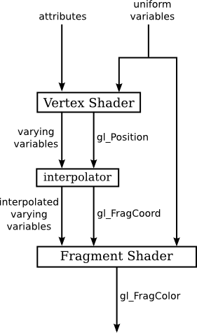
In order for shaders to function we need a mechanism by which we can pass data between them. This mechanism comes in the form of different variable types of which there are 3.
10.4.1 Attribute Variable
Attribute Variables are used in Vertex Shaders to receive per-vertex data from the application on the CPU. This data could include vertex coordinates, normals, colours, and texture coordinates. Each vertex processed by the vertex shader gets its set of attribute values.
10.4.2 Uniform Variable
Uniform Variables are another form of shader variable that provide a way to pass information to either Vertex or Fragment Shaders (or both). Unlike attribute variables, uniform variables keep the same value across the execution of all vertices or fragments in a single draw call. They are commonly used to pass transformation matrices, light information, or global settings to the shaders.
10.4.3 Varying Variable
Varying Variables are used to pass interpolated data from Vertex Shaders to Fragment Shaders. The data passed through varying variables typically include texture coordinates, per-vertex colours, and transformed normals. The rasterizer interpolates the values output by the vertex shader for each vertex of a primitive to generate the corresponding input for the fragment shader.
A varying variable should be declared in both shaders, with the same name and type. This allows the GLSL compiler to determine what attribute, uniform, and varying variables are used in a shader program. For example given a set of vertices we may want to use the interpolated colour for a given pixel and therefore we would use a varying variable.
10.5 Creating a Shader
The following process describes how to create and compile a shader program using OPenGL. The steps involve declaring shaders, compiling them, linking them into a program, and attaching them to the WebGL context for rendering.
10.5.1 Declare
In this step, placeholders for the vertex and fragment shaders are declared using JavaScript. These shaders will later define how vertices are processed and how pixel colors are calculated.
10.5.2 Define a source
You define the actual GLSL (OpenGL Shading Language) code for both the vertex and fragment shaders.
Vertex Shader: This shader processes each vertex’s position and color. It receives attributes like position (a_position) and color (a_color) and passes the color to the fragment shader using a varying variable (v_color). The position is transformed by projection and model-view matrices.
Fragment Shader: This shader determines the color of individual pixels. It receives the interpolated color from the vertex shader (v_color) and sets it as the output color for rendering.
const vertexShaderSource =
`
//Declare local variables
attribute vec4 a_position;
attribute vec3 a_color;
uniform mat4 u_modelViewMatrix;
uniform mat4 u_projectionMatrix;
varying vec3 v_color;
//Define a main method
void main() {
v_color = a_color;
gl_Position = u_projectionMatrix * u_modelViewMatrix * a_position;
}
`
;
const fragmentShaderSource =
`
//Declare local variables
varying vec3 v_color;
//Define a main method
void main() {
gl_FragColor = vec4(v_color, 1.0);
}
`
;10.5.3 Compile
The compileShader function is responsible for taking the shader source code and compiling it into a usable format. It checks for any errors during compilation and logs them to the console if any are found.
function compileShader(gl, type, source) {
    const shader = gl.createShader(type);
    gl.shaderSource(shader, source);
    gl.compileShader(shader);
    if (!gl.getShaderParameter(shader, gl.COMPILE_STATUS)) {
        console.error('An error occurred compiling the shaders: ' + gl.getShaderInfoLog(shader));
        gl.deleteShader(shader);
        return null;
    }
    return shader;
}
10.5.4 Create shader program
This step involves creating a shader program that will combine the compiled vertex and fragment shaders. The shaders are compiled, attached to a program object, and linked together. Error handling ensures that the shaders compile and link properly.
const shaderProgram = createProgram(gl, vertexShaderSource, fragmentShaderSource);

function createProgram(gl, vertexShaderSource, fragmentShaderSource) {
    let  vsh = gl.createShader( gl.VERTEX_SHADER );
    gl.shaderSource( vsh, vertexShaderSource );
    gl.compileShader( vsh );
    if ( ! gl.getShaderParameter(vsh, gl.COMPILE_STATUS) ) {
        throw new Error("Error in vertex shader:  " + gl.getShaderInfoLog(vsh));
    }
    let  fsh = gl.createShader( gl.FRAGMENT_SHADER );
    gl.shaderSource( fsh, fragmentShaderSource );
    gl.compileShader( fsh );
    if ( ! gl.getShaderParameter(fsh, gl.COMPILE_STATUS) ) {
        throw new Error("Error in fragment shader:  " + gl.getShaderInfoLog(fsh));
    }
    let  prog = gl.createProgram();
    gl.attachShader( prog, vsh );
    gl.attachShader( prog, fsh );
    gl.linkProgram( prog );
    if ( ! gl.getProgramParameter( prog, gl.LINK_STATUS) ) {
        throw new Error("Link error in program:  " + gl.getProgramInfoLog(prog));
    }
    return prog;
}
10.5.5 Attach shader objects
The vertex and fragment shaders are attached to the WebGL program object, which groups them together to be used for rendering.
10.6 Transformations
10.6.2 Viewing Transforms
This method places the viewer at the point (eyeX,eyeY,eyeZ), looking towards the point (refX,refY,refZ). The viewer is oriented so that the vector (upX,upY,upZ) points upwards in the viewer’s view. For example, to position the viewer on the negative x-axis, 10 units from the origin, looking back at the origin, with the positive direction of the y-axis pointing up as usual, use
10.6.3 Projection Transforms
Projection transformations convert 3D coordinates into 2D coordinates displayed on the screen, often using perspective or orthographic projections.
10.6.4 Normal Transforms
Normal transformations adjust normals for lighting calculations post model transformations, using the transpose of the inverse of the modelview matrix.
When a surface is transformed in some way, the normal vectors to that surface will also change. However you cant simply apply the same transformations you do on vertices to the normals as seen below
Nevertheless, it is possible to get the correct transformation matrix for normal vectors from the coordinate transformation matrix. It turns out that you need to drop the fourth row and the fourth column and then take something called the inverse transpose of the resulting 3-by-3 matrix. The glMatrix library will compute it for you. The function that you need is normalFromMat4, and it is defined in the mat3 class:
mat3.normalFromMat4( normalMatrix, coordinateMatrix );In this function call, coordinateMatrix is the mat4 that represents the transformation that is applied to coordinates, and normalMatrix is a mat3 that already exists. This function computes the inverse transpose of the rotation/scale part of coordinateMatrix and places the answer in normalMatrix.
The normal matrix should be sent to the shader program, where it is needed to transform normal vectors for use in lighting calculations. Lighting requires unit normal vectors, that is, normal vectors of length one. The normal matrix does not in general preserve the length of a vector to which it is applied, so it will be necessary to normalize the transformed vector.
attribute vec3 a_coords;   // Untransformed object coordinates.
attribute vec3 normal;     // Normal vector.
uniform mat4 projection;   // Projection transformation matrix.
uniform mat4 modelview;    // Modelview transformation matrix.
uniform mat3 normalMatrix; // Transform matrix for normal vectors.
  .
  .  // Variables to define light and material properties.
  .
void main() {
    vec4 coords = vec4(a_coords,1.0);  // Add a 1.0 for the w-coordinate.
    vec4 eyeCoords = modelview * coords;  // Transform to eye coordinates.
    gl_Position = projection * eyeCoords;  // Transform to clip coordinates.
    vec3 transformedNormal = normalMatrix*normal;  // Transform normal vector.
    vec3 unitNormal = normalize(transformedNormal);  // Normalize.
       .
       .  // Use eyeCoords, unitNormal, and light and material
       .  // properties to compute a color for the vertex.
       .
}
10.7 Hierarchical Modelling
To do hierarchical graphics, we also need to save and restore the transformation as we traverse the scene graph. For that, we need a stack. We can use a regular JavaScript array, which already has push and pop operations. So, we can create the stack as an empty array:
We can then push a copy of the current modelview matrix onto the stack by saying
and we can remove a matrix from the stack and set it to be the current modelview matrix with
These operations are equivalent to glPushMatrix() and glPopMatrix() in OpenGL.
10.8 Examples
10.8.2 Lambert Shading
Calculates lighting at a per-vertex level and then uses the interperlator to interperlate colour at every pixel.
const vertexShaderSource = `
    attribute vec3 a_coords;
    attribute vec3 a_normal;
    uniform mat4 modelview;
    uniform mat4 projection;
    vec3 v_normal;
    vec3 v_eyeCoords;

    uniform mat3 normalMatrix;
    uniform vec4 lightPosition;
    uniform vec4 diffuseColor;
    uniform vec3 specularColor;
    uniform float specularExponent;

    varying vec4 fragment_color;

    void main() {
        vec4 coords = vec4(a_coords,1.0);
        vec4 eyeCoords = modelview * coords;
        gl_Position = projection * eyeCoords;

        v_normal = normalize(a_normal);
        v_eyeCoords = eyeCoords.xyz/eyeCoords.w; // (Note: eyeCoords.w is 1 unless modelview is weird)

        vec3 N, L, R, V;  // vectors for lighting equation
        N = normalize( normalMatrix*v_normal );
        if ( lightPosition.w == 0.0 ) {
            L = normalize( lightPosition.xyz );
        }
        else {
            L = normalize( lightPosition.xyz/lightPosition.w - v_eyeCoords );
        }
        R = -reflect(L,N);
        V = normalize( -v_eyeCoords);  // (Assumes a perspective projection.)
        if ( dot(L,N) <= 0.0 ) {
            fragment_color = vec4(0,0,0,1);
        }
        else {
            vec3 color = 0.8*dot(L,N) * diffuseColor.rgb;
            if (dot(R,V) > 0.0) {
                color += 0.4*pow(dot(R,V),specularExponent) * specularColor;
            }
            fragment_color = vec4(color, diffuseColor.a);
        }


    }`;

const fragmentShaderSource = `
    #ifdef GL_FRAGMENT_PRECISION_HIGH
       precision highp float;
    #else
       precision mediump float;
    #endif

    varying vec4 fragment_color;
    void main() {
        gl_FragColor = fragment_color;
    }`;
Remember that lighting calculations are done in eye coordinates. The vector L that points from the surface to the light can be computed as:
where lightPosition is a vec3 that gives the position of the light in eye coordinates, and eyeCoords is a vec4 giving the position of the surface point in eye coordinates. For a viewpoint light, the lightPosition is (0,0,0), and L can be computed simply as normalize(−eyeCoords.xyz).
The eye coordinates for the surface point must be computed by applying the modelview matrix to the object coordinates for that point. This means that the shader program needs to know the modelview matrix; it’s not sufficient to know the combined modelview and projection matrix.
10.8.3 Phong Shading
Calculates lighting at a per-pixel level.
const vertexShaderSource = `
    attribute vec3 a_coords;
    attribute vec3 a_normal;
    uniform mat4 modelview;
    uniform mat4 projection;
    varying vec3 v_normal;
    varying vec3 v_eyeCoords;
    void main() {
        vec4 coords = vec4(a_coords,1.0);
        vec4 eyeCoords = modelview * coords;
        gl_Position = projection * eyeCoords;
        v_normal = normalize(a_normal);
        v_eyeCoords = eyeCoords.xyz/eyeCoords.w; // (Note: eyeCoords.w is 1 unless modelview is weird)
    }`;

const fragmentShaderSource = `
    #ifdef GL_FRAGMENT_PRECISION_HIGH
       precision highp float;
    #else
       precision mediump float;
    #endif
    attribute vec3 v_normal;
    attribute vec3 v_eyeCoords;
    uniform mat3 normalMatrix;
    uniform vec4 lightPosition;
    uniform vec4 diffuseColor;
    uniform vec3 specularColor;
    uniform float specularExponent;

    varying vec4 fragment_color;
    void main() {
        vec3 N, L, R, V;  // vectors for lighting equation
        N = normalize( normalMatrix*v_normal );
        if ( lightPosition.w == 0.0 ) {
            L = normalize( lightPosition.xyz );
        }
        else {
            L = normalize( lightPosition.xyz/lightPosition.w - v_eyeCoords );
        }
        R = -reflect(L,N);
        V = normalize( -v_eyeCoords);  // (Assumes a perspective projection.)
        if ( dot(L,N) <= 0.0 ) {
            fragment_color = vec4(0,0,0,1);
        }
        else {
            vec3 color = 0.8*dot(L,N) * diffuseColor.rgb;
            if (dot(R,V) > 0.0) {
                color += 0.4*pow(dot(R,V),specularExponent) * specularColor;
            }
            fragment_color = vec4(color, diffuseColor.a);
        }
    }`;
To add specular lighting to our basic lighting model, we need to work with the vectors R and V in the lighting diagram. The amount of specular reflection depends on the dot product R·V, which represents the cosine of the angle between R and V. The formula for the contribution of specular reflection to the visible color is:
where s is the specular exponent (the material property called “shininess” in OpenGL). The formula is only valid if R·V is greater than zero; otherwise, the specular contribution is zero.
The unit vector R can be computed from L and N. (Some trigonometry shows that R is given by 2*(N·L)*N − L.) GLSL has a built-in function reflect(I,N) that computes the reflection of a vector I through a unit normal vector N; however, the value of reflect(L,N) is −R rather than R.
The unit vector V points from the surface towards the position of the viewer. Remember that we are doing the calculations in eye coordinates. For an orthographic projection, the viewer is essentially at infinite distance, and V can be taken to be (0,0,1). For a perspective projection, the viewer is at the point (0,0,0) in eye coordinates, and V is given by normalize(−eyeCoords) where eyeCoords contains the xyz coordinates of the surface point in the eye coordinate system. Putting all this together, and assuming that we already have N and L, the GLSL code for computing the color takes the form: